Most 3D printers use leadscrews for at least one axis. These are simple devices that are essentially a steel screw thread and a brass nut that travels on it. However, for maximum precision, you’d like to use a ball screw. These are usually very expensive but have many advantages over a leadscrew. [MirageC] found cheaper ball screws but, since they were inexpensive, they had certain limitations. He designed a simple device that improves the performance of these cheap ball screws.
Superficially, a ball screw looks like a leadscrew with an odd-looking thread. However, the nut is very different. Inside the nut are ball bearings that fit in the grooves and allows the nut to spin around with much less friction. A special path collects the ball bearings and recirculates them to the other side of the nut. In general, ball screws are very durable, can handle higher loads and higher speeds, and require less maintenance. Unlike leadscrews, they are more expensive and are usually quite rigid. They are also a bit noisier, though.
Ball screws are rated C0 to C10 precision where C10 is the least accurate and the price goes up — way up — with accuracy. [MirageC] shows how cheaper ball screws can be rolled instead of precision ground. These screws are cheaper and harder, but exhibit more runout than a precision screw.
This runout caused wobble during 3D printing that was immediately obvious on the prints. Using a machinist’s dial gauge, [MirageC] found the screws were not straight at all and that even a relatively poor C7 ball screw would be more precise.
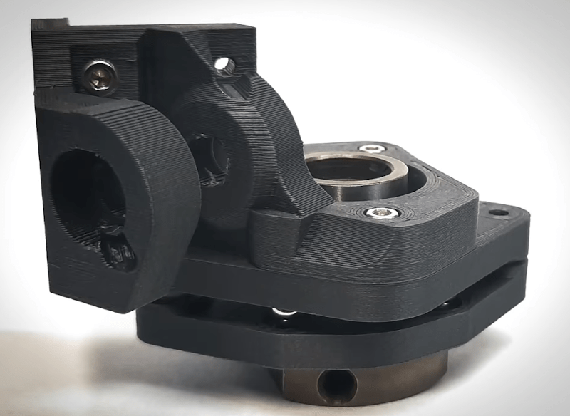
The solution? A clever arrangement of 3D printed parts. ball bearings, and magnets. The device allows the nut to move laterally without transmitting it to the print bed. It is a clever design and seems to work well.
If you want to learn more about ball screws, we can help. Although the accompanying video is dead, Mitsumi had some very good information to share about them, too.


Cool solution for super low loads on ballscrews, though I feel that for loads this low, a simple belt or cable drive would do the same thing for a much lower cost.
Belts and cables have their own set of problems, and rarely approach the resolution of even an inexpensive lead screw.
This is because the primary motion — generally, a steeper operating with 1.8° resolution — is reduced by the pitch of the lead screw, allowing (for example) 0.002″ precision with a 10tpi thread.
i think the point here is that the effective precision is slop-limited. i don’t know how to compare slop between belts and lead screws but i doubt a cheap lead screw is going to get less than 2 mils of slop!
Usually printers use lead screws of some kind on the vertical axis, which lets you use gravity as an anti-backlash measure to take up the slop and gives you more precise motion on the layer thickness axis (where you need more of it). You probably would use a ball screw on that more to reduce friction (so you can move a bit faster) and get a _somewhat_ less extreme gearing more than to gain precision or accuracy.
I was thinking of the backlash issue too, b/c I have ballscrews on a new CNC mill in the basement and it’s soooo much nicer than trapezoid screws for the purpose: lots of back-and-forth motion.
But on the Z of a 3DP, you’re only really ever going up, and backlash almost doesn’t matter, hence the OP’s focus on reliability and maintenance.
It’s funny to see z-wobble still affecting printers. That was the Curse of the Cupcake (and the Darwin!) back in the day because it sat entirely on the screws. And then generations of Mendel and derivatives where people wanted to keep the screws from wobbling around, and constrained them, leading to the “tug-of-war” mentioned in the video…
I love this solution with the magnets and balls, with extra magnets further out for torque. I’m a little surprised that mechanical engineers don’t already have a well-optimized solution for this one: translation in two axes, constrained in the other four.
You still get the same anti-backlash effect from gravity on ballscrew, if there is any to start with. The nut on the ballscrew in the video looks like an anti-backlash nut. His solution introduced direction-dependent axial nut rotation, AKA backlash, that does not appear to be corrected by gravity.
The best Thomson lead screws have a precision falling between C7 and C8, about 76um/300mm linearity, when new. Their standard lead screws are 250um/300mm, or just worse than C10. Another advantage of ballscrews there is that they can better maintain their initial accuracy. There’s plenty of old Monarch lathes still making accurate parts on old leadscrews though.
The reality is that we’re discussing a 3D printer made from aluminium extrusion that doesn’t even have its linear rails bolted correctly to the frame.
> I’m a little surprised that mechanical engineers don’t already have a well-optimized solution for this one: translation in two axes, constrained in the other four.
They do, and the guy showed a version of it, but decided not to built it and went for the magnets and balls instead. It’s a variation of an Oldham coupling.
It’s well proven that belts can provide motion with a lot less slop/backlash than ball screws. Anyone that has done the research on building a CNC or 3D printer from scratch knows this. A quality properly tensioned belt can greatly exceed the precision of a ball screw. The problem with belt drives is they usually add to the complexity of the drive system. So they are usually avoided when possible. Especially in DIY designs.
You are also confusing the resolution with precision…
The pitch on a lead screw or ball screw is the exact same thing as using 2 different sized pulleys on a belt drive. In fact many designs use this approach to drive the ball screw at a different ratio to either increase torque or increase resolution. But I want to emphasize that this has nothing to do with precision. I can have 0.002″ resolution on both a ball screw or a belt drive. However that doesn’t mean I have 0.002″ precision. When you account for backlash, or as this hack is trying to fix “wobble”, your precision is greatly decreased.
My (formerly) Ender 3 Pro uses a belt-driven Z axis, and I can actually print at finer resolutions… more reliably than with cheap lead screws. Gear reduction and steps/mm tuning was all that was required.
The reason I went that route is because the printer sucked with lead screws. I always got banding or shifts on the Z axis, no matter what I did. I replaced the lead screws (twice), I switched to delrin nuts, brass nuts, delrin anti-backlash nuts, brass anti-backlash nuts, new brackets, everything.
Point is: there are applications where belts are vastly superior to cheap lead screws.
That was a very informative video! And an interesting project too.
Thanks for posting!
“This runout caused wobble during 3D printing that was immediately obvious on the prints.”
The only way this would happen is if he was using transport grade ball screws (like the kind used for mobile home jacks) for motion control, which is a bad idea regardless of how much you pay. To be visible like that, the deviation would have to be a significant fraction of a millimeter, which is orders of magnitude above the spec for all motion control ball screw grades.
Looking at his method for measuring “runout” he’s putting a dial test indicator on a part of the nut that is probably not a datum surface – IE not valid for measuring anything. Also, measuring the ball screw horizontally like that will just measure sag, and moving the DTI along the nut like that just measures the nut surface, not the screw. To measure axial runout, he’d have to support the screw vertically and rotate it, measuring the distance from the nut to a parallel surface.
I admire his efforts in re-working things, but I don’t agree that the result is due to what he says it is… more likely it was backlash in the drive train or an issue with the drive motors or even a warped screw due to mounting issues that caused that amount of deviation in position.
Having built using them, I know a C7 rolled screw from a good supplier will far exceed the precision and accuracy of most acme screws, many of which are used to produce flawless 3d prints.
While you are right his measurement technique as shown can bring errors into the measure, the test he did does show the order of magnitude these really really cheap ballscrews came with, which massively exceeds the slop level in his measurement jig. As does the image of it rotating vertically and wobbling hugely (i.e. it is bent).
My biggest complaint is if you are going to use magnets like that, and want no maintenance it makes very little sense to just glue them in – one day that glue will fail, but in those hard to see spots – his 3d prints really should have had a layer under the magnet (or even chamfered magnets) so the magnet can never pull itself loose. I also think its probably the worst method for ‘fixing’ such bad wobble I can imagine, flexture systems are so much better at being stiff in all the right directions..
i have seen plenty of leadscrews that have a lot of runout, or are bowed in their center… it would be nice to have an adapter like this for a regular T8 screw.
There, I fixed it for you with cheap ACME screw. https://i.imgur.com/ZnipGdg.jpg
Some good ingenuity here.
The solution is questionable though. @17:24 I can clearly see Z backlash has been introduced. The wobble wings have reduced fluctuations in nut rotation, but they do not prevent it totally. You can see that the nut rotates one direction going up, and the opposite when going down. What that means is that during the transition from one direction to the other, the screw is spinning, but instead of the nut moving up or down, it is rotating whilst maintaining the same Z position. Only after the nut rotation stops does the vertical motion start. It might be acceptable in Z for many 3D printers though because layers are usually only printed in one direction. It would be interesting to know whether the nut remains rotated as an entire layer gets printed, or whether it drifts back to zero because of the magnets (which would result in each layer growing over time). It might be fine since the magnets are fighting the weight of the bed and part. I would not use this on X or Y though. The better solution would have been the plates with radial ball grooves since they allow movement in the plane whilst ensuring an angular constraint, but who can resist a 3D printed solution containing magnets?
An even better solution since he has a dial indicator, would be to lay the screw in a cradle of two wooden v-blocks, and use a wooden or rubber mallet to carefully tap it straighter. I wouldn’t ever recommend this to chase tenths in expensive screws, but when you’re many thousandths (visibly!) out on a cheap screw, you really don’t have anything to lose.
I was also wondering why his linear guides didn’t constrain the movement. It looks to me like the screw might be a little big for the rail size, but not horrendously so. The rails are mounted to extruded aluminium channel which has poor tolerance for flatness, but should provide enough stiffness for the rail. However I notice that he only bolted the rail into the channel every fourth hole. That’s a major problem, especially when the screw is big and eccentric. The rails are likely bending to conform to the screw. Adding 300% more bolts would increase its stiffness significantly.
Some other observations:
Please do not test the rigidity of ballscrews with your hands like that. Precision screws from reputable manufacturers are usually checked for straightness and corrected as necessary. You will be able to bend them out of tolerance if you try. Also, I cringed when he dropped one ballscrew against another. You don’t want dings in your screws.
I disagree with his pro/con assessment that ballscrews are more rigid than leadscrews. He’s effectively saying, “I compared a thin leadscrew to a thick ballscrew, and the ballscrew is more rigid, so all ballscrews are problematically rigid.” For a given material, tempering and diameter they will be pretty close. Likewise, he should use EP2 grease instead of oil, and the noise would be much reduced. (But, what would I expect from a video that included WD40 as an example lubricant?). Also, ballscrews do need maintenance. They need a shot of grease into the nipple on the nut every now and then. The excess will ooze out removing the microscopic particles of steel worn from the balls and the channels in the nut.
The only advantages that leadscrews have over ballscrews are cost and the vastly reduced backdrive in vertical applications; and the second of those is moot – brakes and weight compensation (counterweights, or gas springs) are inexpensive solutions there. It really comes down to precision versus price, and the costs of maintaining those precisions.
There is an error in the ball return channel animation too. I don’t know it came from, but it is not correct for that ballscrew. The animation shows a single return crossing a single channel of several circuits. Simple visual inspection informs that there is not enough depth to the metal for that to be the case, and his nut contains 3 plastic plugs, not two. Most single channel nuts use an exterior tube to return the balls. Machining an internal tube as the animation shows is not trivial. His nut contains 3 individual circuits each making a single turn around the screw before being returned via one plug. The hole that the plug fits into is drilled such the ball hops out of the screw thread and returns to the other side of it as the screw rotates.
It has an advantage too – preload. When a single channel nut is used, the balls can only load against one side of the channel in the nut – that which they are being pressed against by the screw. When the screw reverses direction, they shift to press against the opposite side. Since the balls have to move, the channel has to be slightly larger than the balls, and that space results in backlash. A double nut (literally two nuts back to back) uses compression to push each nut outward such that they each preload one side of their balls, thus eliminating that backlash. His nut though is already preloaded – the threads in the middle circuit are cut with a tiny axial shift relative to the other two. It’s in effect a triple nut. That’s one reason why the introduced nut rotation is so bad. He started with zero vertical backlash, and now has more.
It might seem that I didn’t like this video, but on many levels it was great. The production is really very slick, with good use of animations, video clips of manufacturing etc, and it did a good job of explaining what ballscrews and leadscrews are, even if I dispute some of his pro/con findings. It’s obvious that a lot of effort went into making it. The fact that the video results from a dubious solution to the wrong problem caused by a lack of fundamental understanding (and bolts) does not detract from that.
It used to be possible to buy rolled C5 ballscrews from a UK company IBL. They got absorbed into Thomson. When I looked to replace a heavily worn D16mm 5tpi L18.5″ ballscrew with nut, I was quoted nearly $2400 – without shipping, duties or taxes from Germany. Precision is expensive. It’s possible that replacement would have been ground, since Thomson don’t list C5 rolled ballscrews in their product lists. Needless to say, I gulped, cleaned and reballed the existing screw, and have since sourced another from eBay.
Some general rules of thumb:
Assume rails are wet noodles until bolted sufficiently to a stiff surface. Use all the bolt holes.
Extrusion is never flat nor straight. If you mount a (notionally straight and flat) 12mm thick steel rail to a bent 25mm thick aluminium extrusion will that rail stay straight and flat? You could probably do wonders to flatten an extruded aluminium mounting face with a few grades of wet’n’dry sandpaper on a granite countertop. Yeah, it might not look so pretty if you grind through anodization, but hey.
No amount of magnetic trickery can fix poor fundamentals. Get your structure stiff and square first, with flat mounting faces.
Go down at least one size for your ballscrew. If you have 20mm rails, 15/16mm ballscrew is good, assuming that you need to handle cutting forces. Since 3D printing incurs no cutting forces, you don’t need beefy screws. Try a 12mm screw with a 20mm rail. If you have 12mm rails, try an 8mm screw. Make the ballscrew conform to the rail, not the other way around.
There are ballscrew refurbishing companies that regrind them then use the largest balls that will fit. I’ve seen some claiming they can grind rolled screws and improve their accuracy to match a ground screw, with the combined cost of the rolled screw plus grinding being less than a fully ground screw.
Some ballscrews have every other ball undersized. Such “spacer” balls are used to reduce friction but also decrease accuracy and load capacity. Replacing the spacer balls with full size ones will increase the load capacity and accuracy. The number of balls usually has to be reduced by 1 or 2 to accommodate having them all full size.
Thank you! I was shaking my head throughout the video for all the reasons you listed. Hobbyists love to overcomplicate things for the sake of feeling smart. Any good engineer knows that simplicity is the key to every design. I love the concept, but it’s a solution born out of self inflicted problems. Sadly, those problems are only obvious to someone with a manufacturing or engineering background.
Random Participant: “These ball screws are weaksauce, let’s beef them up a bit ! ”
A statement that you could have entirely different reactions to, depending on whether you’re at a hackathon or a BDSM party.
I saw this a few weeks ago and wondered why he went down that path to solve it.
Considering that he actually has linear rails to constrain any motion not in the Z-axis, why not just leave the ballscrews unconstrained at one end. The end can wiggle around due to runout without applying any significant sideways forces to the linear rail – other than maybe vibration which can be managed though speed.
Do a trick that’s done with long leadscrews. Mount the screw under some tension to keep it from sagging when horizontal. That can also pull a slight bend straight. Tension also keeps a bend or sag from whipping at high speed.
For tensioning a vertical ball screw with an aluminum extrusion frame I’d use some beefy extrusion like 40×40 mm then machine a steel rocker to mount at the top. Put the ball screw bearing mount on one side and on the other side have a threaded rod going down to the base for applying the tension. The goal is to apply enough force to pull the ballscrew straight without causing the aluminum extrusion support tower to bend.
It is radial runout – the variation is in the direction of the radius of the screw.
Good timing and overview with article comments. More re-enforcing why I’m still hesitant to disassemble the printer carriages and belt drives for just the 8mm SS rods. Now thinking might stick with the original plan and try to use in a multi-functional design… maybe adding linear bearings onto the shafts whatever winds up being the sled/carriage/slide/gantry. Will keep in mind for future designs however that are larger with more loading on the drive.