Stepper Killer Killer Killed, Repair Attempted

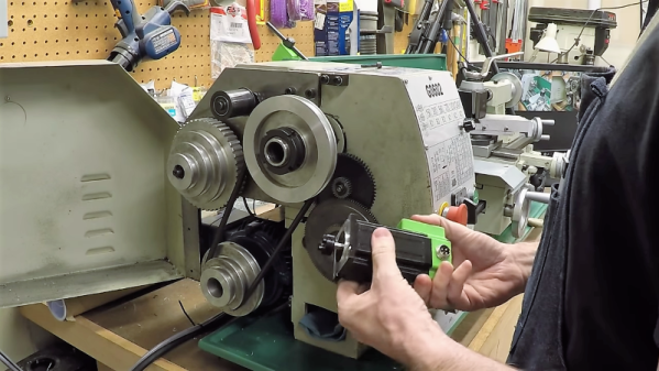
The low-cost servo motor in [Clough42]’s lathe’s electronic leadscrew bit the dust recently, and he did a great job documenting his repair attempts ( see video below the break ). When starting the project a few years ago, he studied a variety of candidate motors, including a ClearPath servo motor from Teknic’s “Stepper Killer” family. While that motor was well suited, [Clough42] picked a significantly lower-cost servo motor from China which he dubbed the “Stepper Killer Killer”.

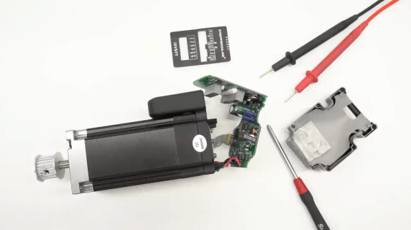
He does a very thorough post-mortem of the motor’s integrated servo controller, checking the circuits and connections on the interface PCB first. Not finding any obvious problem, he proceeds to the main PCB which contains the microcontroller, motor driver transistors, and power supplies. There is no visible damage, but a check of the logic power supply shows 1.65V where 3.3V is expected. Looking at the board with a smart-phone mounted IR camera, he quickly finds the bad news — the microcontroller has shorted out.

Continue reading “Stepper Killer Killer Killed, Repair Attempted”

Electronic leadscrew

Electronic Lead Screws – Not Just For Threading Anymore

An electronic leadscrew is an increasingly popular project for small and mid-sized lathes. They do away with the need to swap gears in and out to achieve the proper ratio between spindle speed and tool carriage translation, and that makes threading a snap. But well-designed electronic leadscrews, like this one from [Hobby Machinist], offer so much more than just easy threading.

The first thing that struck us about this build was the polished, professional look of it. The enclosure for the Nucleo-64 dev board sports a nice TFT display and an IP65-rated keyboard, as well as a beefy-looking jog wheel. The spindle speed is monitored by a 600 pulses-per-revolution optical encoder, and the lathe’s leadscrew is powered by a closed-loop NEMA 24 stepper. This combination allows for the basic threading operations, but the addition of a powered cross slide opens up a ton more functionality. Internal and external tapers are a few keypresses away, as are boring and turning and radius operations, both on the right and on the left. The video below shows radius-cutting operations combined to turn a sphere.

From [Hobby Machinist]’s to-do list, it looks like filleting and grooving will be added someday, as will a G-code parser and controller to make this into a bolt-on CNC controller. Inspiration for the build is said to have come in part from [Clough42]’s electronic leadscrew project from a few years back. Continue reading “Electronic Lead Screws – Not Just For Threading Anymore”

Peek Behind The Curtain Of This Robotic Mouse

At first glance, this little animatronic mouse might seem like a fairly simple affair. A door opens, our rodent friend pops its head out, looks around, and goes back in. But just like in The Wizard of Oz, a strategically placed curtain is hiding the impressive array of gadgetry that makes the trick possible.

Creator [Will Donaldson] has put together a fantastic write-up of just what went into creating this little fellow, and we think you’ll be surprised at just how serious the mechanics involved are. Take for example the rig that provides horizontal motion with a NEMA 17 stepper motor mated to a 200 mm leadscrew and dual 8 mm rail assembly that would like right at home as part of a 3D printer.

The star of the show rides atop a beefy sliding carriage assembly made of printed components and acrylic, which is linked to the door via a GT2 timing belt and pulley in such a way that it automatically opens and closes at the appropriate time. To inject some life into the puppet, [Will] stuffed it with a pair of SG90 servos in a sort of pan-and-tilt arrangement: the rear servo turns the mouse’s body left and right, while the forward one moves the head up and down.

An Arduino Uno controls the servos, as well as the stepper motor by way of a TB6600 controller, and optical limit switches are used to make sure nothing moves out bounds. [Will] is keeping the CAD files and source code to himself for the time being, though we imagine a sufficiently dedicated mouseketeer could recreate the installation based on the available information.

This would appear to be the first animatronic mouse to grace the pages of Hackaday, but we’re certainly no strangers to seeing folks imbue inanimate objects with lifelike motion.

Continue reading “Peek Behind The Curtain Of This Robotic Mouse”

Improving Cheap Ball Screws

Most 3D printers use leadscrews for at least one axis. These are simple devices that are essentially a steel screw thread and a brass nut that travels on it. However, for maximum precision, you’d like to use a ball screw. These are usually very expensive but have many advantages over a leadscrew. [MirageC] found cheaper ball screws but, since they were inexpensive, they had certain limitations. He designed a simple device that improves the performance of these cheap ball screws.

Superficially, a ball screw looks like a leadscrew with an odd-looking thread. However, the nut is very different. Inside the nut are ball bearings that fit in the grooves and allows the nut to spin around with much less friction. A special path collects the ball bearings and recirculates them to the other side of the nut. In general, ball screws are very durable, can handle higher loads and higher speeds, and require less maintenance. Unlike leadscrews, they are more expensive and are usually quite rigid. They are also a bit noisier, though.

Ball screws are rated C0 to C10 precision where C10 is the least accurate and the price goes up — way up — with accuracy. [MirageC] shows how cheaper ball screws can be rolled instead of precision ground. These screws are cheaper and harder, but exhibit more runout than a precision screw.

This runout caused wobble during 3D printing that was immediately obvious on the prints. Using a machinist’s dial gauge, [MirageC] found the screws were not straight at all and that even a relatively poor C7 ball screw would be more precise.

The solution? A clever arrangement of 3D printed parts. ball bearings, and magnets. The device allows the nut to move laterally without transmitting it to the print bed. It is a clever design and seems to work well.

Continue reading “Improving Cheap Ball Screws”

Benchtop Lathe Gets An Electronic Leadscrew Makeover

The king of machine tools is the lathe, and if the king has a heart, it’s probably the leadscrew. That’s the bit that allows threading operations, arguably the most important job a lathe can tackle. It’s a simple concept, really – the leadscrew is mechanically linked through gears to the spindle so that the cutting tool moves along the long axis of the workpiece as it rotates, allowing it to cut threads of the desired pitch.

But what’s simple in concept can be complicated in reality. As [Clough42] points out, most lathes couple the lead screw to the spindle drive through a complex series of gears that need to be swapped in and out to accommodate different thread pitches, and makes going from imperial to metric a whole ball of wax by itself. So he set about building an electronic leadscrew for his lathe. The idea is to forgo the gear train and drive the leadscrew directly with a high-quality stepper motor. That sounds easy enough, but bear in mind that the translation of the tool needs to be perfectly synchronized with the rotation of the spindle to make threading possible. That will be accomplished with an industrial-grade quadrature encoder coupled to the spindle, which will tell software running on a TI LaunchPad how fast to turn the stepper – and in which direction, to control thread handedness. The video below has some great detail on real-time operating systems on microcontrollers as well as tests on all the hardware to be used.

This is only a proof of concept at this point, but we’re looking forward to the rest of this series. In the meantime, [Quinn Dunki]’s excellent series on choosing a lathe should keep you going.

Continue reading “Benchtop Lathe Gets An Electronic Leadscrew Makeover”