In the most simple computer system architecture, all control lies with the CPU (Central Processing Unit). This means not only the execution of commands that affect the CPU’s internal register or cache state, but also the transferring of any bytes from memory to to devices, such as storage and interfaces like serial, USB or Ethernet ports. This approach is called ‘Programmed Input/Output’, or PIO, and was used extensively into the early 1990s for for example PATA storage devices, including ATA-1, ATA-2 and CompactFlash.
Obviously, if the CPU has to handle each memory transfer, this begins to impact system performance significantly. For each memory transfer request, the CPU has to interrupt other work it was doing, set up the transfer and execute it, and restore its previous state before it can continue. As storage and external interfaces began to get faster and faster, this became less acceptable. Instead of PIO taking up a few percent of the CPU’s cycles, a big transfer could take up most cycles, making the system grind to a halt until the transfer completed.
DMA (Direct Memory Access) frees the CPU from these menial tasks. With DMA, peripheral devices do not have to ask the CPU to fetch some data for them, but can do it themselves. Unfortunately, this means multiple systems vying for the same memory pool’s content, which can cause problems. So let’s look at how DMA works, with an eye to figuring out how it can work for us.
Hardware Memcpy
At the core of DMA is the DMA controller: its sole function is to set up data transfers between I/O devices and memory. In essence it functions like the memcpy function we all know and love from C. This function takes three parameters: a destination, a source and how many bytes to copy from the source to the destination.
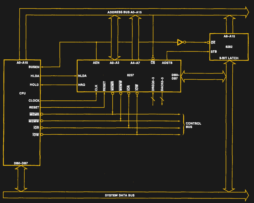 Take for example the Intel 8237: this is the DMA controller from the Intel MCS 85 microprocessor family. It features four DMA channels (DREQ0 through DREQ3) and was famously used in the IBM PC and PC XT. By chaining multiple 8237 ICs one can increase the number of DMA channels, as was the case in the IBM PC AT system architecture. The 8237 datasheet shows what a basic (single) 8237 IC integration in an 8080-level system looks like:
In a simple request, the DMA controller asks the CPU to relinquish control over the system buses (address, data and control) by pulling HRQ high. Once granted, the CPU will respond on the HLDA pin, at which point the outstanding DMA requests (via the DREQx inputs) will be handled. The DMA controller ensures that after holding the bus for one cycle, the CPU gets to use the bus every other cycle, so as to not congest the bus with potentially long-running requests.
The 8237 DMA controller supports single byte transfers, as well as block transfers. A demand mode also allows for continuous transfers. This allowed for DMA transfers on the PC/PC AT bus (‘ISA’).
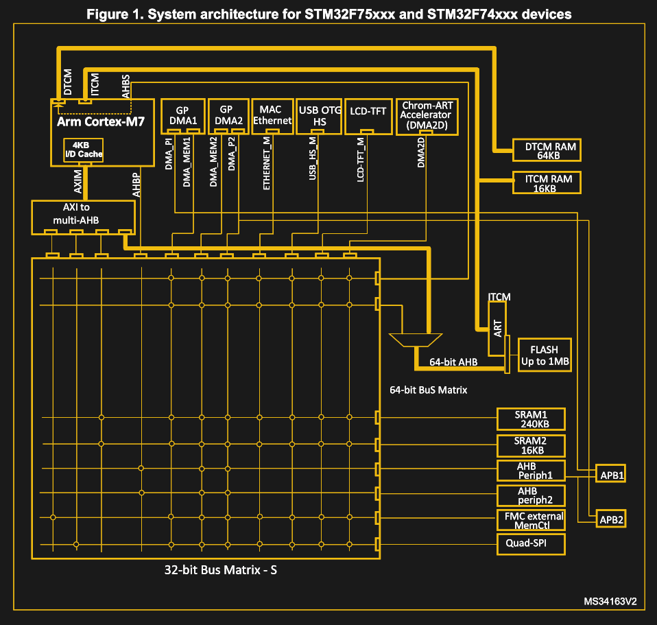 Fast-forward a few decades, and the DMA controller in the STM32 F7 family of Cortex-M-based microcontrollers is both very similar, but also very different. This MCU features not just one DMA controller, but two (DMA1, DMA2), each of which is connected to the internal system buses, as described in the STM32F7 reference manual (RM0385).
In this DMA controller the concept of streams is introduced, where each of the eight streams supports eight channels. This allows for multiple devices to connect to each DMA controller. In this system implementation, only DMA2 can perform memory-to-memory transfers, as only it is connected to the memory (via the bus matrix) on both of its AHB interfaces.
As with the Intel 8237 DMA controller, each channel is connected to a specific I/O device, giving it the ability to set up a DMA request. This is usually done by sending instructions to the device in question, such as setting bits in a register, or using a higher-level interface, or as part of the device or peripheral’s protocol. Within a stream, however, only one channel can be active at any given time.
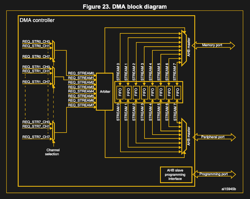 Unlike the more basic 8237, however, this type of DMA controller can also use a FIFO buffer for features such as changing the transfer width (byte, word, etc.) if this differs between the source and destination.
When it comes to having multiple DMA controllers in a system, some kind of priority system always ensures that there’s a logical order. For channels, either the channel number determines the priority (as with the 8237), or it can be set in the DMA controller’s registers (as with the STM32F7). Multiple DMA controllers can be placed in a hierarchy that ensures order. For the 8237 this is done by having the cascaded 8237s each use a DREQx and DACKx pin on the master controller.
Snooping the bus
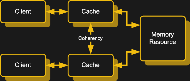
So far this all seems fairly simple and straight-forward: simply hand the DMA request over to the DMA controller and have it work its magic while the CPU goes off to do something more productive than copying over bytes. Unfortunately, there is a big catch here in the form of cache coherence.
As CPUs have gained more and more caches for instructions and data, ranging from the basic level 1 (L1) cache, to the more recent L2, L3, and even L4 caches, keeping the data in those caches synchronized with the data in main memory has become an essential feature.
In a single-core, single processor system this seems easy: you fetch data from system RAM, keep it hanging around in the cache and write it back to system RAM once the next glacially slow access cycle for that spot in system RAM opens up again. Add a second core to the CPU, with its own L1 and possibly L2 cache, and suddenly you have to keep those two caches synchronized, lest any multi-threaded software begins to return some really interesting results.
Now add DMA to this mixture, and you get a situation where not just the data in the caches can change, but the data in system RAM can also change, all without the CPU being aware. To prevent CPUs from using outdated data in their caches instead of using the updated data in RAM or a neighboring cache, a feature called bus snooping was introduced.
What this essentially does is keeping track of what memory addresses are in a cache, while monitoring any write requests to RAM or CPU caches and either updating all copies or marking those copies as invalid. Depending on the specific system architecture this can be done fully in hardware, or a combination of hardware and software.
Only the Beginning
It should be clear at this point that every DMA implementation is different, depending on the system it was designed for and the needs it seeks to fulfill. While an IBM PC’s DMA controller and the one in an ARM-based MCU are rather similar in their basic design and don’t stray that far apart in terms of total feature set, the DMA controllers which can be found in today’s desktop computers as well as server systems are a whole other ballgame.
Instead of dealing with a 100 Mbit Ethernet connection, or USB 2.0 Fast Speed’s blistering 12 Mbit, DMA controllers in server systems are forced to contend with 40 Gbit and faster Ethernet links, countless lanes of fast-clocked PCIe 4.0-based NVMe storage and much more. None of which should be bothering the CPU overly much if it all possible.
In the desktop space, the continuing push towards more performance, in especially gaming has led to an interesting new chapter in DMA, in the form of storage-to-device requests, e.g. in the form of NVidia’s RTX IO technology. RTX IO itself is based on Microsoft’s DirectStorage API. What RTX IO does is allow the GPU to handle as many of the communication requests to storage and decompressing of assets without involving the CPU. This saves the steps of copying data from storage into system RAM, decompressing it with the CPU and then writing the data again to the GPU’s RAM.
Attack of the DMA
Any good and useful feature of course has to come with a few trade-offs, and for DMA that can be mostly found in things like DMA attacks. These make use of the fact that DMA bypasses a lot of security with its ability to directly write to system memory. The OS normally protects against accessing sensitive parts of the memory space, but DMA bypasses the OS, rendering such protections useless.
The good news here is that in order to make use of a DMA attack, an attacker has to gain physical access to an I/O port on the device which uses DMA. The bad news is that any mitigations are unlikely to have any real impact without compromising the very thing that makes DMA such an essential feature of modern computers.
Although USB (unlike FireWire) does not natively use DMA, the addition of PCIe lanes to USB-C connectors (with Thunderbolt 3/USB 4) means that a DMA attack via a USB-C port could be a real possibility.
Wrapping Up
As we have seen over the past decades, having specialized hardware is highly desirable for certain tasks. Those of us who had to suffer through home computers which had to drop rendering to the screen while spending all CPU cycles on obtaining data from a floppy disk or similar surely have learned to enjoy the benefits that a DMA-filled world with dedicated co-processors has brought us.
Even so, there are certain security risks that come with the use of DMA. In how far they are a concern depends on the application, circumstances and mitigation measures. Much like the humble memcpy() function, DMA is a very powerful tool that can be used for great good or great evil, depending on how it is used. Even as we have to celebrate its existence, it’s worth it to consider its security impact in any new system.


Nice writeup, learned something as i was only familiar with the 8237 (from the PC-XT era where the dma also was used for DRAM refresh (in stead of a dedicated dram-controller).
“These make use of the fact that DMA bypasses a lot of security with its ability to directly write to system memory. The OS normally protects against accessing sensitive parts of the memory space, but DMA bypasses the OS, rendering such protections useless.”
Performance vs security. Just ask Spectre.
Yeah, firewire was bad about that but Thunderbolt / USB-C is less risky as those interfaces operate trough an IOMMU, which restricts the memory locations that a DMA call can access. So barring sloppy coding, buggy hardware, or other such problems, the attacker doesn’t have much access to the target. This does allow access some memory, so if you have more than one peripheral attached to the same port (EG, one of those hubs that will include a network interface, some USB ports, display interfaces, etc), there isn’t much they could do.
Sloppy coding? When? Surely such a thing is impossible! (except I see it every damn day)
I was thinking the same thing. And it does seems that some platforms in some cases do make use of the IOMMU to restrict devices from performing any DMA unless their drivers allow for memory control features (visualization of DMA addresses). That being said, it seems like those devices could still read$write whatever they want in those spaces that are allowed by those drivers and exploit bugs, and from there cascade into attacks where writing into OS/kernel spaces is a real possibility.
Hopefully IOMMU can be leveraged further to help IO DMA requests never get access to places they shouldn’t be going all the time!
Overall, as said above, it seems to be a constant situation of “lets be performant first and secure later” for the consumer space… (spectre reference).
The DMA and PIO features of the RP2040 / Raspberry Pi Pico are a great way to learn this stuff. My current project is rendering to a Macintosh Classic CRT, and with DMA copying the framebuffer to the PIO TX FIFO in a loop, it doesn’t require CPU intervention. It even holds the last frame if the program crashes, or during debugging. So useful!
No mention of Thunderspy ?
Wouldn’t any memory mapped IO play havoc with a cache? The value at a location can change even if you don’t write to it, or even access it with DMA. So bus snooping (as I understand it) wouldn’t work.
There are non-cachable areas of memory space in the MMU table for those cases.
e.g. The memory in your GPU card address space can change as the GPU has separate pocessors. Can’t snoop if video memory is larger than the memory mapped window (256MB). Not to mention that it’ll be an entire different section if the 256MB of access window is moved elsewhere via PCI BAR.
Nice overview article. As far as I recall, PCI Bus and its successors abandoned DMA and instead supported multi-processor style bus arbitration, bus mastering, virtual address translation, cache coherence protocols, and VLSI implementation that the AT/ISA DMA design could not anticipate. Also AT/ISA DMA introduced wait states at some bus clock speeds in order to maintain compatibility with slower legacy devices and effectively neutralizing benefits of higher clock speeds. Prior to PCI, “Bus wars” brought to attention bus architecture DMA related issues such as synchronous vs asynchronous operation, coded vs decoded bus cycle signals , fetch and deposit vs fly-by DMA, data transfer size and alignment, cascading/chaining together multiple DMA transfers, and backward compatibility with older devices.
It’s always funny to hear DMA being touted as good because the CPU is free to do other things – and then you go and look at typical DMA example code for most microcontrollers and the CPU just spins waiting on “are you done yet.” (On more modern systems with heavy cache layers, OK, there are advantages to freeing the CPU).
But really, the performance advantage for DMA isn’t that the CPU is free to do other things. It’s that there’s only one bus transaction instead of two. With a PIO read, for instance, the CPU has to fetch the data from the peripheral (transaction one) and then it has to write the data to memory (transaction two). Even if you don’t need the CPU for other things, the DMA’s going to be faster.
Most architectures are designed to be optimized for DMA as well, too, so even though you theoretically *could* get decent performance out of PIO accesses, the system just isn’t designed for it. If you imagine a (classic) PCI setup where the memory’s *much* faster than the PCI bus, performance-wise it’d be perfectly fine to have the CPU handle a read, because the second transaction (memory) would be super-short. Except systems *aren’t designed* to buffer PCI reads, and so (by default) the PIO read throughput is *pathetic* because you only get one transfer per PCI cycle. They *are* designed to buffer PCI writes, so on those systems doing a DMA for a write transaction isn’t nearly as much of an improvement.
Those examples are poor. I have used DMA with ping pong buffering taking care of collecting fresh data while processing previous batch. I have used 2-3 DMA channels doing different things.
IRQ CPU usagde could get really high once they reache over tens of housands of transfers per seconds. Tens of microseconds in each IRQ can add up quickly.
> It’s that there’s only one bus transaction instead of two.
Actually 3 if you count CPU data/instruction fetch for running the transfer loop for small micro without caches. DMA doesn’t have the overhead so could burst faster in theory.
As has been noted, anyone hanging around waiting for the conclusion of a DMA task is a fucking idiot who should be permanently banned from writing code on anything other than a shitty Arduino. That’s THEIR style. You don’t even need involve DMA to make this point – if, on a MCU, you wait FOR ANYTHING EVER that is expected to take more than a few CPU cycles, YOU’RE DOING IT WRONG. Yield to something else and come back to check later – or if you’re SO timing-sensitive, use an interrupt. A PROPERLY PRIORITISED ONE, please. Capisce…?
Nice article, some code examples would’ve been nice :)
years ago, I designed a system that used the first 16-bit microprocessor, the National PACE (nice chip; looked like a Data General Nova 1200). I did a DMA controller for it that didn’t have to steal time from the CPU — it snuck onto the memory bus during subcycles when the CPU wasn’t using it. Totally transparent. The PACE had a ten-microsecond major cycle time(!), so it needed all the cycles it could get.
DMA was big in military systems in the 60’s. Such as as digital signal processing in a wing pod listening for radar and SAM signals, and the DMA sending data words over differential serial lines. So all the DSP horsepower was in an external pod, and the computer just had to decode the data structures returned. So every 10 ms or so, you’d have a new block of data.