We’re all too familiar with the 3D printing post-processing step of removing supports, and lamenting the waste of plastic on yet another dwindling reel of filament. When the material is expensive NinjaFlex or exotic bio-printers, printing support is downright painful. A group at USC has come up with a novel way of significantly reducing the amount of material that’s 3D printed by raising portions of the bed over time, and it makes us wonder why a simpler version isn’t done regularly.
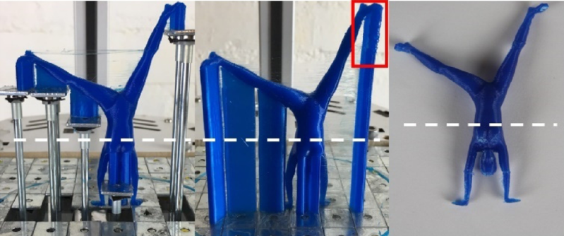
In the USC version, the bed has a bunch of square flat metal pieces, with a metal tube underneath each. The length of the tube determines the eventual height of that square. Before the print is made, the bed is prepared by inserting the appropriate length tubes in the correct squares. Then, during the print, a single motor pushes a platform up, and based on the height of the pin, that portion of the bed raises appropriately, then stops at the right height.
 This is a significant savings over having a matrix of linear motors or servos to control each square, at the cost of having to prepare the pins for each print.
But it has us wondering; since CURA and other slicing software have the ability to pause at height, what if the slicing software could allow for the placement of spacer blocks of a known size? The user would have a variety of reusable spacer blocks, and position them in the software, and the slicer would build the support material starting on top of the block. It could print a rectangle on the base layer to aid in proper placement of the blocks during printing, and pause at the correct heights to let the user insert the blocks. At the end of the print a lot less support material has been used.
For situations where you want to leave your print to run unattended, or if the cost of the material is low enough that it doesn’t justify the effort, then maybe this isn’t worth it. Another problem might be heating that platform, though since only support material will be printed on it, some curling won’t matter much. What do you think?


It would be pretty easy to do this without needing to pre-set tubes of various lenghts under the bed:
Instead of a grid of tubes, have a grid of (very fine pitch) threaded rod, with a pair of magnets at the top. Then near the extruder, have a pair of magnets connected to a stepper motor. When you want to raise a threaded rod, you place the actuator pair of magnet on top of one of the threaded rod pair of magnets, and rotate the stepper motor, which raises the threaded rod by rotating it.
This way, you can raise the supports each layer after it’s done printing, the *exact* same way you’d do with printed supports. The only difference is instead printing supports, you go to that position and rotate the magnet actuator.
This feels super easy/straightforward to implement, if I had any time for this I’d totally attempt it. The most difficult part is modifying Slic3r so it does the work, but I have experience with that too. If anyone plans to implement this, contact me at wolf.arthur@gmail.com, and I’ll help you if I can.
Hmm I like your magnet drive from the head idea, not sure how practical it will be – magnets near hot stuff means careful magnet selection, without feedback a magnetic coupling could really easily skip steps and the support wouldn’t be where it should be, magnetic couplings don’t always actually rotate the way they ‘should’ either and its more mass on the print head.. All probably solvable, and cheap if it works, its just the one extra motor.
I’d say more elegant than my separate core x-y to drive the rods, though I’d argue that my method is easier to actually implement reliably.
You can use vacuum instead of magnets if temperature is a concern (I generally print cold on PEI, but yes, heated bed are a common thing, and here you’d have to heat the top of each screw separately, which could be a hassle).
Or you can have it be fully mechanical: have a hole/dent in the “head” of your screw, and have the hotend’s tip insert itself in there, and rotate/make circles to rotate the screw (like a finger in a rotary phone). No need for an extra motor, all you need is a very neatly made and precisely machined bed of screws with the correct geometry for the heads.
With a small spring, you can have the hole-for-hotend be filled normally, and only go down when the hotend presses on it. You can have everything ( screw head, and hole-for-hotend’s-springed-cap ) be fully/perfectly flush with the bed (you can have it all have a millimeter of PEI on top of it, then once everything is assembled, you machine/surface it all on a mill ).
Then you can heat all of that together to the right temperature (might want copper/brass screws?).
There *are* mechanical solutions to all this it seems, it’s just about somebody actually taking the time/effort to do it and show the world.
Indeed, lots of potential solutions, many that will require a very high level of precision in the creation. I think you can easily avoid the spring loaded bed bit – just have the “finger in the rotary phone” bit be shallow and small enough to easily bridge over with print when its needed, will need a pretty stiff Z axis to provide enough bite into such a shallow dent but it is possible.
Also perhaps you don’t need to heat all the tops separately – heat the common guide plate for the rods and let them conduct the heat up, with the right multi material the outside of the rods can be pretty cool and not radiate too much. The thermal expansion shouldn’t matter too much, as plenty of slop in the mechanism isn’t going to effect the print at all, so just make it have wide enough tolerance to deal with any differential expansions. You are quite right though you don’t need a heated bed for everything, so keeping to the right materials perhaps better to just omit it. I wonder if a heated chamber would be sufficient to overcome the lack of heated bed… I don’t know if anybody has ever tried just a heated chamber…
Seems to me the simplest to build solution is still just putting another x-y stage underneath to drive each rod, and probably significantly cheaper to build too – the precision machining is going to cost a heap, or just cost you in time… But hey our time is free, and machining is fun!
Isn’t it fun engineering with our keyboards, without having to do any of the hard work of actually building anything ? :) Let’s build a rocket next!
Indeed, blackpowder? Hydrogen? Perhaps might I suggest you seem like a salami fuel rocket kind of person?
Seriously though I’d love to give some of these ideas a go myself, its the never ending battle for enough space, time, energy, materials/money…
Very clever and for the right filaments this could be really good. But the ones that just won’t stick to this surface, or rapidly curl off unheated surfaces I suspect you will end up with lots of failed prints as the support material fails to stay where it should.
I like the idea of hand placed blocks better than the pre-prepared rods too – will be much harder to accidentally put in one that is too long or short as you can see how far the printer has got for that insertion – an immediate sanity check. If you are going to have rods deployed by the printer seems like making each rod have a threaded rod driven from underneath by another core x-y with a rotating tool would keep it pretty cheap and scalable to any print bed volume, worst you might have to do is put a small pause in your printing g-code while the rods are cranked up.
Also seems to me a bullseye pattern of concentric rings split into sections would probably make a better pattern for the raising lifts – shouldn’t need so many of them to provide good support points for most prints (making a few assumptions like the lowest point of the model is always centered, you are willing to print support material with some overhang of the lifted bed sections), and because they can be larger they can also be made heated or surfaced with a better material to help with adhesion of the target filament relatively easily.
However overall I think the conical slicing method might be the best way for most tasks, that’s a relatively simple printer redesign (or even no redesign if you can put up with shallower cone shapes), and copes pretty will with any overhang from whats been seen of it. Does look like it needs more work in the slicing software to really get the best out of it though, where this is barely a deviation from normal printing so the software changes are trivial. Worth pointing out though I have personal experience of neither system (yet).
Heated beds are going to give way to heated chambers now that the pertinent patents have expired.
Those patents weren’t a hindrance to those making a heated enclosure, it only prevents specific implementations.
Hand-placed blocks and columns that can be placed and held in place with a magnetic bed would be great. Requires a good number of different sizes, tho. Would need a nice grid on the bed so you can find where to place them.
a small heated bed wouldn’t be crazy
Wait, so, instead of using cheap, recyclable* filament, we install carefully machined blocks and pins. And a motor.
It’s clever, but I can’t see it gaining traction.
*for appropriate values of “recyclable”.
I see this being used for industrial 3D printing or for a 3D printing service such as shapeways where the savings in support material might actually offset the cost. Not so much for a home gamer.
Unless you plan on using materials that require bed heating, the parts for this mechanical assembly can probably be printed themselves. I’m fairly certain you can avoid adding an extra motor if you lock the bottom platform a fixed distance form the z axis.
Another take on this is to use 3 stepper motors and piece of plywood that form a base the any printer could rest on. The stepper could then tilt the base plus or minus 15 degrees in any direction so that supports are not needed. This way the base could be shifted based on a few methods using gcode or just sensors looking at the z axis.
This is where commercial 3d printing makes hobby setups look like toys. With something like an mjf or sls the print is fully supported in the extra unused print material. I think that instead of trying weird solutions for fdm the hobby market should be trying to figure out how to get sls or mjf into homes.
It’s much more difficult to make a cheap mjf or sls machine than it is making a cheap fdm/fff one, there are good reasons why one is in makers’ hands and the others aren’t.
One needs just a heating element and a few super simple mechanical parts, the others need a *laser* or jet system. Also, for one the consumable is cheap filament, and for the other it’s hard to handle/procure powders.
There are good reasons why these have different prevalence, and it’s not as simple as “figuring out” to get this gap closed.
It’s like saying the hobby market should be “trying to figure out how to” get rollerblades to go as fast and carry as much as trucks. You can be super smart, but there are limits to how much the laws of physics will let you do/accomplish.
I dont know, I think that in the same way everything can be extruded, everything can be sinthered… why we are not trying alternatives to extruders, the laser is even simpler than an extruder…
This is job calls for spiralift! https://m.youtube.com/watch?v=AukVObyIF90
*Extremely* cool. Would need to be somewhat miniaturized, not sure how easy that would be.
Would it be possible to place the printer on a base that has 3 stepper motors. The base controller could then be loaded with the gcode and would tilt the printer when need to avoid supports. That way no slicer mods would be needed.
Yes but the software and firmware to do that is complicated.
Very cool! I think individually threading the rods for during-printing adjustment would add way more cost to this than it’s worth, and the reason spacer blocks were being considered were for a more economical option not requiring an tool head or an extra axis of motion. I do wonder though; has anyone considered the possibility of using an array of lockable contour gauge in place of tubes?
End effector in print-head, magnet on end effector.
Grid of squares, each square on telescoping rod…car antennas!
Magnet clicks onto square, raise/lowers square to desired height.
Slide to left, slide to the right, and the magnet lets go.
Tool-changer in print-head selects magnet or extrusion.
There, saved you money.
Buy me coffee!
Who knew test panels had a use!
its funny I was doing some prints a couplle of weeks ago that needed lots of support and was thinking of ways to add blocks to act as supports.
And here we are some one else has already been working on it
Nice idea, like a pin array (toy). If you did use a pin array you could tilt in 90 degrees then use mechatronics to push each pin into position before locking the array and rotating it back to act as topologically variable print bed. You’d just have to ensure that you allow clearance for the print head, unless you did the tiling and pin pushing in stages too, as the model was built up. Anything that reduces the total time the device spends extruding is going to have an economic benefit so finding the trade-off sweet spot is key. This works best in a headed printing chamber, as others have pointed out, no need to heat the pins directly but there are ways of doing that if required, such as illumination from below with an array of heat lamps and the bottom of each pin head being black.
If any of the above is original and not patented it is my intent that it be covered by the CERN Open Hardware License (OHL). BTW what is the default legal status for an original idea published in a HAD comment?
Undoubtedly zero protection, as it should be. Ideas are ten a penny. Let me know when you’ve built something.
Besides, how are you going to going to put your name on the licence? Just write “correct horse battery staple”?
It isn’t about me (𐂀 𐂅 of the HAD tribe) , it is about ensuring that all makers and hackers have free access to the concepts and that they can’t be locked up for 20 years and only used on proprietary products under heavy licencing conditions that are out of the reach of smaller scale innovators. Duh! We are not all as selfish and ego driven as you are.
Think about this, if we are going to make Mars colonisation happen it is going to take a really huge leap in automation and compaction of industrial processes because we can’t move half of civilisation across the solar system but we need similar levels of capabilities there. If the spirit of that does not resonate with you then you are probably commenting on the wrong web site.
First step on the road to https://www.youtube.com/watch?v=0qcED35LL8I
I use hand cut foam regularly for this same purpose. PETG sticks great to it. Just wedge it in place (somehow) often for long bridges.