Homebrew 8-bit computers tend to have fairly limited displays, often one or more seven-segment displays and an array of LEDs to show the values of RAM or perhaps some other states of the computer. [Duncan] is in the process of building just such an computer, but wondered if there was a way to create a more visually appealing display while still keeping the computer true to its 8-bit roots. With some interesting TTL logic he was able to create this addressable RGB LED display to some remarkable results.
The array works by controlling the WS2812B LED strips with a specific timing cycle which was pioneered by [Tim] for a different project. [Tim] was able to perform this timing cycle with some simple Assembly code, which means that [Duncan] could convert that code into TTL gate logic relatively easily. Using 74LS02 NOR chips gets the job done as far as timing goes, and the pulses are then fed into a shift register and support logic which then creates the signal for the LED strips.
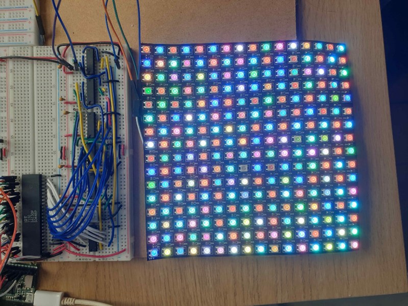
When everything is said and done, [Duncan] has a fully addressable 16×16 RGB LED array as a display for his 8-bit computer without violating any of his design principles and keeping everything to discrete TTL logic chips and a stick of RAM. It’s a unique method of display that might go along really well with any other homebrew computer like this one that’s also built with 74LS chips.


I’ve been contemplating something similar but with a long chain of serial to serial shift registers, maybe 64 or 128 bits each, then selecting between two clock speeds. A slow clock for filling the registers with the slow and relatively imprecise hardware of my home brew machine and then a faster clock with just the right timing to actuate the LEDs successfully. Then I potentially have no need for calculating nops and clever software, I can just send the right bits and let the hardware do the talking.
I’d love to see some of the homebrew retro PCs use period correct CRT controllers which can still be had on ebay to output composite that you can connect to an actual CRT TV/Monitor, or even the composite of a modern TV. Some like the RC-2014 have a composite adapter, but the adapter is just a raspberry pi that acts as a terminal emulator, then outputs to the Pi’s composite out. Something just rubs me so wrong about this kind of setup, using a PI that is thousands of times more powerful than the host computer just to output composite video. Even some of the PCs from that period didn’t even have CRT controller chips, but just used the processor and some discreet TTL logic to generate the composite signal. TRS-80 was this way. I think something like a quarter of the ICs on the TRS-80 main board were used just for this composite video generation. I’ve seen a few others that use the 40pin DIP propeller microcontroller to generate composite/VGA signals, still feels wrong, but at least looks more period correct when you have a home brew PC out on display. I’d have to wonder how hard it would be to implement the same basic composite out TTL logic in something like a DIP CPLD or PLA at least in that case you’ve recreated the original TTL circuitry in a modern chip that doesn’t eat up half a square foot of board space that it would take to do it in actual TTL logic.