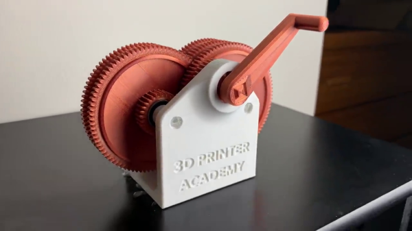
[Steven] at the 3D Printer Academy has been working on a variety of different gear designs. He recently embarked on a series of experiments to see how fast he can spin a 3D-printed gearbox.
After testing several kinds of gear teeth, gear diameters, and gear spacing, he finally struck upon an 81:1 ratio gearbox. It has six gears: five stepped gears and one drive gear on the input shaft. First tests are accomplished with a 3D-printed handle, similar to a hand crank used to start really old cars. But unlike those cranks, [Steven]’s doesn’t have any release provision. While the handle can be removed, it can’t be removed while spinning.
We think it would be helpful to revise the drive shaft coupling method, allowing the handle or drill to be easily removed from the gearbox once it’s attained speed. This would be more convenient, and it seems prudent from the workbench safety point of view as well.

[Steven] manages to get the final gear spinning at 7000 RPM in video #2 of the series by hand cranking it “as fast as he can”, a speed measured by using the metronome app on his smartphone. He begins driving the gearbox with an electric drill in video #3, with some mixed but promising results. We think he will ultimately succeed in his goal of a high-speed, electric-drill-driven gearbox after a few more tests. If you want to have a go at this yourself, the design files are posted online.
How fast do you think he can eventually get this gearbox spinning? Are there any physical limitations of the assembly or due to the 3D printing materials/process? We certainly know that high torque can tear 3D-printed gearboxes apart, but how does the speed affect things? Let us know in the comments below.


