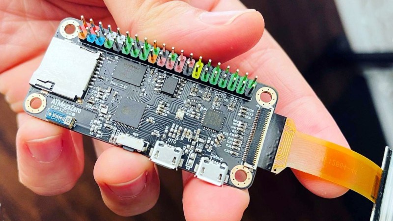
The ATMegaZero ESP32-S2 is currently being funded with a campaign on GroupGets, and it’s a microcontroller board modeled after the Raspberry Pi Zero’s form factor. That means instead of the embedded Linux system most of us know and love, it’s an ESP32-based development board with the same shape and 40-pin GPIO header as the Pi Zero. As a bonus, it has some neat features like a connector for inexpensive SSD1306 and SH1106-based OLED displays.
Being able to use existing accessories can go a long way towards easing a project’s creation, and leveraging that is one of the reasons for sharing the Pi Zero form factor. Ease of use is also one of the goals, so the boards will ship with CircuitPython (derived from MicroPython), and can also be used with the Arduino IDE.
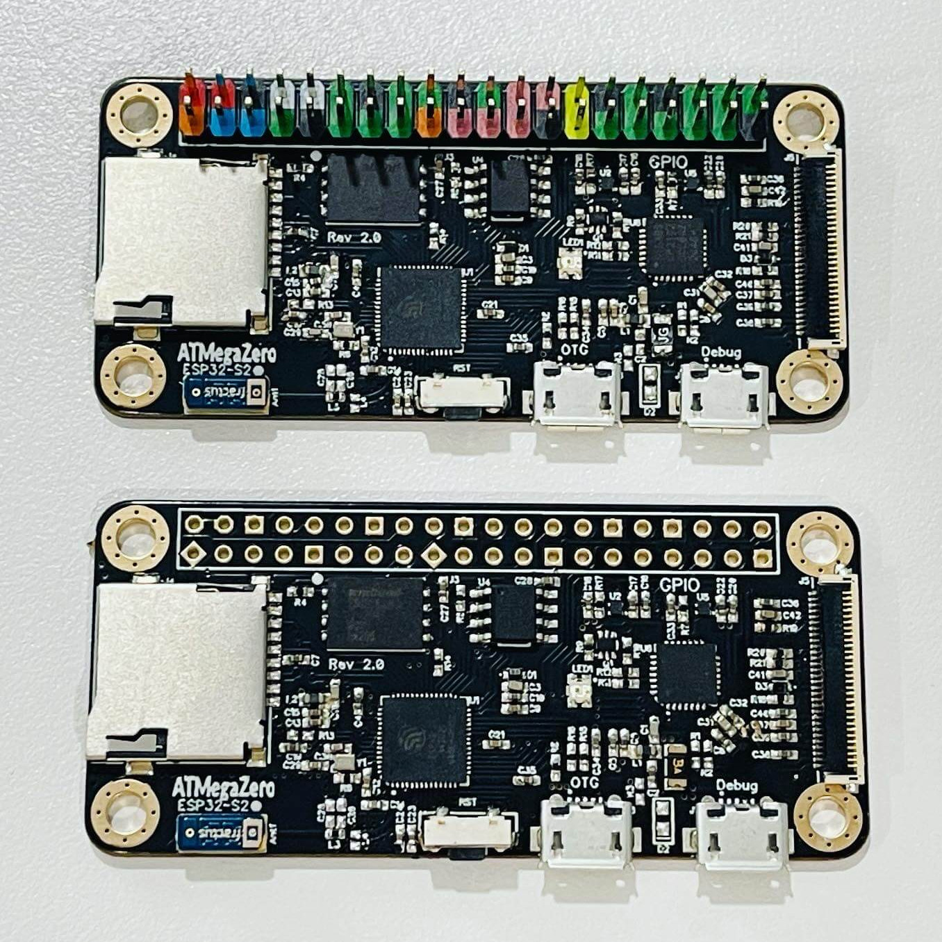
If a microcontroller board using the Pi Zero form factor looks a bit familiar, you might be remembering the original ATMegaZero which was based on the Atmel ATMega32U4, but to get wireless communications one needed to attach a separate ESP8266 module. This newer board keeps the ATMegaZero name and footprint, but now uses the Espressif ESP32-S2 to provide all the necessary functions.
CircuitPython has been a feature in a wide variety of projects and hacks we’ve seen here at Hackaday, and it’s a fine way to make a microcontroller board easy to use right out of the box.


“With CircuitPython, there are no upfront desktop downloads needed. Once you get your board set up, open any text editor, and start editing code. It’s that simple.” – CircuitPython website.
Right up until you change the white space on a single line in an if block from say tab to space, then you will be scratching your head for hours trying to understand why your code doesn’t work.
Any time I’ve accidentally done that, Python has immediately reported an “inconsistent use of tabs and spaces” error and the exact line the error is on. Mu, the Adafruit-recommended CircuitPython IDE, points to any line which uses tabs and tells you not to use them. It’s not that hard to deal with.
Wouldn’t spaces use more memory than tabs? Not at all a big deal for PCs, but it sounds like a step backwards for microcontrollers.
Technically, sure, but even for a pretty big app it’d amount to a mere couple of hundred of bytes. If you were that hard constrained, it’d probably be best to just use C++.
That said, I dunno how CircuitPython or MicroPython handle things, but at least CPython does allow you to use tabs instead for indentation as long as you’re consistent about it — no mixing-and-matching spaces and tabs for indentation. It’s against the styleguides, but it’s a matter of taste so they allow it.
IIRC they do get compiled down to bytecode so shouldn’t be an issue
Python code is compiled, so unless you’re running out of harddrive space because of using spaces rather than tabs (???), this is not an issue.
Possibly yes, but this is python. So tabs don’t exist and according to them you’re somehow a heathen for thinking tabs are a thing or that you should want to use them.
[citation needed]
Handy if it reports the problem, it certainly never used to on the system I was using, so diagnosing some clown’s addtition of a space to the start of a tabbed line as a hilarious prank was interesting (especially since the system was embedded in a GSM modem and had no debugger). I did retire 5 years back, so things have evidently changed, but I will never regard typographic layout as an appropriate arbiter of block structure, I saw different editors do so many varied things to source code in the last 47 years to trust it. I guess growing up on Algol60 leaves a penchent for curly brackets that will never go away (and having to use card columns in FORTRAN IV, despite using paper tape, was just retrograde).
Then you flip on the option in your text editor/IDE to show all whitespace characters, and you find it.
Welcome to one of Python’s greatest misfeatures,
Well, Python is one of _those_ languages where a good IDE comes in handy. Last time i checked Pycharm was free and it still is the ultimate Python IDE.
Or emacs, or VSCode
(Yes, I just recommended a Microsoft product – but VSCode is FOSS and I’ve been pleasantly surprised.)
What we really need are: Displays.
There are tons of cheap mobile phones. With displays. Is it that difficult to design something around an existing display? CUBOT C20 goes for 120 € and has a 6.3 Zoll 1080*2246. So the display + CPU can’t be that expensive. It only needs some command interface on that CPU and a connector.
Please. Take my money. (OK, not much money, please.)
I may be wrong, but I believe the problem with those high resolution displays on phones is that there aren’t that many manufacturers of the actual displays. Same thing for TVs and monitors, there may be plenty of shells but crack them open and you’ve got LG, Samsung, Sharp, and maybe a couple left that can mass produce on a level to keep costs down. If argue that drivers would be more accessible to reuse those old mobiles like we see with old laptop screens but if the screen works it’s likely the processor and all internals still work too so why not just reuse the whole thing and drive components with USB and an attached microcontroller? Save all the extra work.
Totally agree. We need some way to use phone/tablet displays.
I know it is difficult, as it is very difficult to get the documentation and specifications, but there is a lot of them about now..
The “tons of phones” is the problem. A lot of different models of displays, each with its specific cable. A board made for one model ( say, Google Pixel xyz ) would need at least an adapter to connect the display from a Samsung Galaxy, for example. And different displays are hard to find in some places of the world, with the usual sources catering more to the most popular models.
The problem is that smartphone displays usually have a MIPI-DSI or eDP interface, which is not common in low-end MCUs nor easy to work around. Even the lower-resolution displays (for example 1024×600 popular in low-end 7″ tablets) have a RGB-TTL interface which requires you to push out pixels all the time, they have no bulitin frame RAM.
The MIPI screens also don’t seem to have a common connector nor pinout (I’d be happy to be proven wrong though)
/me totally clueless about anything of the smartphone ecosystem. I simply thought: it has a display. it has something that drives that display. it is capable of at least to run some crappy bloated OS.
So strip off the baseband stuff, the camera, most of the memory etc. and add some updatable µ-OS/graphics kernel software and some SPI interface.
Let the production line run this for an entire Sunday. Profit.
There’s also routinely a lot of display-device-specific timing customizations.
I used to maintain an AOSP-derivative firmware (Omnirom) for a multitude of phones. Just upstream kernel changes meant that somehow, timings that worked great on a Qualcomm CodeAurora kernel for a particular MIPI display would cause severe flickering/tearing artifacts with any newer/mainline kernel.
I don’t think anyone ever quite figured out correct timings for the panel that would work with a newer kernel.
There are literally hundreds of cheap display modules available out there, and a lot of them are supported by CircuitPython’s displayio library. There are at least 10 CircuitPython devices made by Adafruit with built-in displays, and many more 3rd-party ones. TFT, LCD, e-ink, OLED or even SHARP Memory Displays, take your pick.
The “TTGO T-Display” is a really nice ESP32 devboard, with a reasonably high resolution tft, and the are sub $10.
Those screens look great! They 135×240 IPS displays that are addressed by SPI using the ST7789V driver. I have one of the TTGO boards and was surprised by the quality of the image on these displays.
Or you could save a few bucks and just buy a Rpi zero and get a more powerful everything.
If you want less power consumption, the ESP is a better choice.
Not really, there are many disadvantages to the Rpi. uSD card socket with no lock, Corrupt the uSD if sudden power loss, Does not have extended temp rating, long time to boot, Much larger current consumption.
it is possible to avoid the risk of SD card corruption on power failure by running the OS completely from RAM, see for instance: https://github.com/ali1234/rpi-ramdisk
Had to comment simply on the coloured/colored GPIO pin header. What a great idea! Probably not truly original (but the first time I’ve seen it), and would make finding the right pin much easier and avoid making simple mistakes that can lead to disaster (for example with the Pi GPIO header).
Just don’t solder it in the wrong way around! :O
So it has a mention of 3 products in its name, two of which (atmega and pi zero) it isn’t – I find this amusing 😁
Looks like a nice selection of added features, and the S2 is a great chip with good CircuitPython support: I’ve had a MagTag with local Covid-19 numbers on my fridge for months now, and the newer builds of CircuitPython have really improved the battery life too. (Every so often I grab a USB power bank and plug it in to recharge the little 420mAh lipo that came with it in the Adabox.)
Not only that, but embedding someone else’s trademark in your product name is dubious (as someone who has done this in the past, and had to rebrand as a result, I speak with experience)
great but this working more eficient? less power consumption?
how compare this? for example I can send email , wifi, for week in one charging and rpi0 dont?
Make a stacking version of this with pogo pins between pi USB OTG for communication and I’m sold. I always end up wanting a real time interface for my projects, but really like the pizero form factor.
Pity. It would make more sense as a Zero clone, to replace the Zero in robotics projects, if it had a camera port and not the display port.