Some of you may remember a recent project that featured on these pages, a 555 timer reproduced using vacuum tubes. Its creator [Usagi Electric] was left at loose ends while waiting for a fresh PCB revision of the 555 to be delivered, so set about creating a new vacuum tube model of a popular chip, this time the ubiquitous 741 op-amp. (Video, embedded below.)
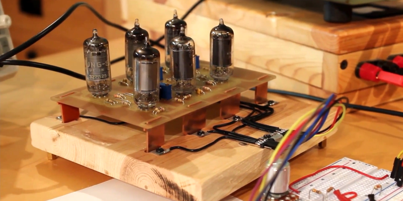
The circuit is fairly straightforward, using six small pentodes. The first two are a long-tailed pair as might be expected, followed by two gain stages, then a final gain stage feeding a cathode follower with feedback. It’s neatly built on a PCB with IC-style “pins” made from more PCB material, then put in a huge replication of an IC socket on a wooden baseboard.
The result is an op-amp, but not necessarily a good one. He looks at the AC performance instead of the DC even though it’s a fully DC-coupled circuit, and finds that while it performs as expected in a classic op-amp circuit it still differs from the ideal at higher gain. The frequency response is poor too, something he rectifies by replacing the feedback capacitor with a smaller value. Sadly he doesn’t look at its common mode performance, though we’d expect that without close matching of the tubes it might leave something to be desired.
It’s obvious that this project would never be selected as an op-amp given the quality of even the cheapest silicon op-amp in comparison. But its value is in a novelty, a talking point, and maybe a chance to learn about op-amps. For that, we like it.
We covered the vacuum tube 555 when details of it emerged, but if op-amps are your bag we’ve looked at a simple one very closely indeed.
Thanks [Emily] for the tip.


Well, the 6dj8 tubes he’s using are used with an anode voltage of 24V, and they were designed to work with a typical voltage of 90V. If he increases the voltage, the tubes should work better.
I see no 6DJ8 (ECC88) here, the board is populated with 6AU6 (EF94) – and horrible sockets that will crack the tube bases.
It’s in the video clip. 7 minutes in.
Whatever that is, it doesn’t match the board layout or the final assembly.
The board is actually exactly what is shown on the schematic only with the addition of 100 ohm resistors for the screen grid on the little pentodes I’m using. The software I use to simulate only had a 6DJ8, which is why they’re different.
Other than that though, the circuit design and values are all identical!
You’re right, I am indeed running 6AU6 tubes here! The simulation software I use (TINA) only has a 6DJ8 model, so that’s what the schematic is showing.
As for the “horrible” sockets, I’m currently building a vacuum tube computer using these 1mm PCB pin headers and have plugged and unplugged tubes countless times without ever breaking a single tube. They are infinitely better than the cheap ceramic sockets you can find at places like AliExpress or on eBay, though admittedly not quite as good as the proper vintage Belton sockets. Though, proper Belton sockets tend to be a couple bucks a tube, and on the computer I’m already up to 80 tubes and looking at the build going well into the hundreds, so saving a little on the sockets makes a huge difference!
Still, I have yet to break a tube plugging it into these little socket headers!
Fixed contacts + thermal expansion = mechanical stress. There’s a warning about that in most tube manuals.
Ah, true, some concessions had to be made. The primary difference here is that everything that I build is usually only on for an hour a day at most. While that mechanical stress from thermal expansion may eventually kill some tubes, I have some in boards I’ve been using on and off for a year now that still work great.
I think because I’m using the tubes so infrequently, that it takes so much longer for the mechanical stress to build up and it’ll be years before I lose one to that.
Conversely, I have killed about 20 or so tubes by simply dropping them cause I’m a massive klutz, haha!
What is the exact name/description of the pin sockets?
Where you bought them?
Thanks.
I’m using Harwin H3161 1mm PCB header sockets.
I get them from Mouser, but they should be available through multiple sources!
You are right in that I’m running incredibly low voltages and that’s definitely pushing the limits of how the tubes can react.
As for the 6DJ8s, I don’t have a 6AU6 model for the simulation program I use (TINA), so I built the schematic and simulated it using the 6DJ8 model. Real world performance of the 6AU6 is surprisingly close to the simulated performance of the 6DJ8, so it works out rather well here!
well you row with the oars you’re given.
I’ve never used TINA before but apparently you can import SPICE models.
http://www.frank.mif.pg.gda.pl/other/docs/Koren_Tubes.cir
TINA isn’t the best simulation software out there, but I found it to be the most user-friendly. And with importing a few tube sockets, it simulates well enough to get me close enough on a circuit design idea that I can then breadboard and test it out!
And that is how engineering meets art!
Thank you!
Why not just build a tube opamp? That’s how they existed originally. And I think simpler than this.
How is this a tube 741? Can it drop in as a replacement? Does it actually translate the internals of the 741 to tubes?
Between tubes and ICs, there were opamp modules, I had one about the size of a matchbox. I don’t know if it was discrete components or something fancier.
SWTP sold opamps, made with discrete transistors. Early seventies, it was in Radio Electronics Ithink. I can’t find a date, but the July 1972 issue of Wireless World describes the same circuit.
If we spend our time rebuilding the past, where does that.leave the present and future?
SWTPC’s 199A preamp. Coupled with their 207A amps they were claiming .01% IM distortion
Correction:198A
The object isn’t necessarily to build an op-amp, but to build one using outddated technology, to make it an interesting piece of functional art and to have fun in the process of creating it. If it matches the functionality of the monolithic integrated circuit, then that is a bonus.
I have used tube op-amps (a tall, skinny beast on a ceramic 10-pin base). Fun, intricate and rather boring to look at unless to took off the aluminium sleeve.
The op amp modules I used (Burr Brown) in the 1980’s were built using selected and matched transistors on open frame bases (like a can transistor without the top cover) and weighed in at a couple of ounces of resin encapsulation and aluminium base-plate.
as my ha’penneth of wisdom – without rebuilding the past, we have no hope of understanding the workings of the present, and will not even begin to see how to design the future.
Thank you!
And you’re absolutely right, there was actually three primary goals to this build.
Learn more about OpAmps, try to build the largest DIP socket ever, and make something that looks hilarious!
At the end of the day, I had a ton of fun experimenting with this and learned a huge amount about OpAmps, the 741 and how to build random stuff in the shop!
Also, I love your quote, I may have to steal that!
I actually mention this in the video, but this is indeed a replica of a tube OpAmp. It’s a copy of the old Philbrick K2-W, but I had to make a few modifications to get it to work at such an incredibly low plate voltage. The Philbrick K2-W needed +300V and -300V, so 600 volts of potential difference, but here I’m using just +24V and -12V. Much safer, but that brought with it some issues, the primary of which was a massive limit in the amount of gain I could get. So, I needed to add in a few more gain stages to get the open loop gain up to acceptable levels.
As for it being a 741 replica, well, that was me being a bit cheeky. It is pin compatible with the 741, meaning 7 of the 8 pins are laid exactly as they are on the 741. However, I needed to pipe in -12V for bias, so the NC pin became ground and the V- pin is where the -12V is run in.
As for the offset null pins, I have actually provided added that in, but I haven’t given it a proper test yet. Normally, I would have the two cathodes tied together and then a 220k to ground from there. To make the offset null pins usable, I tie the cathodes together with a 100 ohm resistor and then have a 470k ohm resistor to ground from each cathode. Then, going into the cathodes are big 10M resistors that connect up to the offset null pins. This way an input on those pins can be used to alter the cathode potential slightly to hopefully help biasing!
I’m not sure if I explained that all that well, but I hope that helps shed some light on it that I didn’t quite get to mentioning in the video!
No need for a ground pin. The series heater string is a convenient low-impedance voltage divider.
There are tube opamps made by Philbrick in the 60s, likely performing much better than this. So, this is not a new thing, interesting as it may be.
Yes, the Philbrick K2-W
But they require 600V for normal operation
Here is the datasheet: http://philbrickarchive.org/k2-w_refurbished.pdf
I mean, with “Vacuum Tube” in the title, I’m super curious what kind of “new” thing you were expecting!
This is actually a copy of the old Philbrick K2-W that you’re thinking of, but I had to make a few modifications to get it to work at such an incredibly low plate voltage. The Philbrick K2-W needed +300V and -300V, so 600 volts of potential difference, but here I’m using just +24V and -12V. Much safer, but that brought with it some issues, the primary of which was a massive limit in the amount of gain I could get. So, I needed to add in a few more gain stages to get the open loop gain up to acceptable levels.
In the end I had a ton of fun building it, learned a bunch about OpAmps and the history of OpAmps, and I learned that you can really get tubes working at massively low voltages pretty well!
not only gain limits, but also far less linear.
Yup!
There’s a few ways I could potentially tackle this to make it work a bit better. Triode strapping the pentodes really helps with their linearity, but also just running some dual triodes could help as well (and save space in the process).
But, and I don’t really mention this in the video, the primary driving force behind the design was to redesign the comparators on the 555 project, and I decided to toss one a PCB for funsies!
What I’d like to know is where the tubes come from these days. Source? Sources?
China, Russia, military surplus and junkyards, the last ones are usually sold at Fleabuy for absurd prices.
The tubes I’m using here are little 6AU6 sharp cutoff pentodes. Audiophiles are often hunting down dual triodes, so these little pentodes are largely ignored, and they were produced in insane quantities, so there’s still a bunch of used ones out there pulled out of old TVs, radios, equipment, etc. I just keep a keen eye out on eBay and can often find lots of the more undesirable tubes for super cheap!
George Philbrick made very good opamps in 1952 with vacuum tubes. See:
https://images.computerhistory.org/revonline/images/X91.82p-03-02.jpg?w=600
I used his first transistor-based Opamps in 1967 to make automatic remote data logging for Broadcast Transmitters. Wow.. I can amplify DC and OFFSET DC accurately ! They were great but too expensive for general audio work until the early RCA 3029 opamps and then the 741.
Using my new-found ability to program in BASIC on the Dartmouth time-sharing system, I learned how to design good multipole audio filters that used voltage-follower Opamps. I got these weird Fairchild matched-pair transistors in an IBM giveaway bin, and made opamps that ran at +- 24 VDC and had plenty of headroom at broadcast levels. I made 5-pole high pass filters that were flat at 100 Hz (AM Broadcast proof test frequency) and then went down like a stone. Peter Paul and Mary’s “Leaving on a Jet Plane” used to sound horrible on car radios and table radios. The bass in that mix flapped their cones around like.. paper. Also “Magic Carpet Ride” was trouble. For a few years in the 60’s those filters were Top Secret at WMCA, WALL and WTLB.
Joe Sousa has a great repository of the Philbrick contributions: http://www.philbrickarchive.org/
Regards, Terry King
…In The Woods In Vermont
The one who dies with the most Parts LOSES! WHAT DO YOU NEED??
In one of his earlier videos, he covered that very opamp. The performance of his opamp is limited by his conscious decision to limit himself to low voltages, something which he conducted a good deal of research and experimentation to optimize even to get where it’s at. That is covered in detail his other videos.
Yup, Winston nailed it!
This OpAmp is essentially a direct copy of the Philbrick K2-W OpAmp, though I had to make a few changes to run it at such low voltages.
The reasoning behind the 24V is that I’m a huge klutz and terrified of high voltages, but I also love vacuum tubes. So, I wanted to see if they could work at lower voltages, and it turns out they tend to do pretty well! The reasoning behind choosing 24V over a different low voltage was that I wanted to be able to run four tube heaters in series, so I could build modules of four tubes. But, I also needed a negative bias, so I chose -12V to give me the ability to run two heaters in series.
In this way, I can build modules of any size really as long as the number of tubes is even!
That’s wonderful! Kudos! 😃
Always imagined making a tube based comparator circuit for a hamcomm-style modem.. Interfacing programs like JV-Fax, GSHPC (DOS) and so on with tube technology would be somewhat cool!
Thank you very much!
This circuit actually works much better as a comparator and in open loop configuration can go up to about 10 kHz before there slew rate starts to become a problem. Makes a wonderful square wave from about 2V to 22V though!
A great art project! Running at such low voltages impacts performance, but is certainly safer to play with, given all that exposed wiring.
But I do think there are better performing tube opamps. I remember playing with a Heathkit EC-1 analog computer in college. I think it only used 1-2 tubes per opamp.
The vertical amp in any oscilloscope is essentially a decent opamp. You might look at some of the vacuum tube ‘scopes for inspiration.
Thank you so much!
And I definitely wanted this to be a much more manageable voltage. With just +24V and -12V on the board, even my accident prone, careless self can’t get hurt, haha.
The Heathkit EC-1 I believe used a triode pentode combo for their OpAmps, but I’m not entirely sure what made them OpAmps instead of just run of the mill amplifiers, as it seemed like they only had one input. I need to do some more reading of the Manual for it to really wrap my head around them.
This one is actually a copy of the old Philbrick K2-W OpAmp, but since I’m at such a low voltage, I had to add in two more gain stages to make up for the massive lack of gain. I could get the tube count down to three if I used some dual triodes like the 6CG7, but the little 6AU6 pentodes are so much cheaper, and honestly, the more tubes in use, the cooler it looks, haha.
You’re right; I looked up the manual for the Heathkit EC-1. It had nine amps with only inverting inputs. To make an opamp with + and – inputs, you used two amps; one wired to invert and the other to sum the direct and inverted inputs.
The later Heathkit EUW-19 had five true vacuum tube opamps with +/- inputs. Each used a pair of 12AX7’s, with +/-300v supplies, as you mentioned. But they got a gain of 21,000 and a flat frequency response to 100 KHz.
Note: “Space charge” tubes were specifically designed for low plate voltages. They have a lot more gain at 12v than normal tubes being run at 1/10th the ratings. These tubes were built for things like car radios before the age of transistors. See http://www.junkbox.com/electronics/lowvoltagetubes.shtml for more info. You can sometimes find them pretty cheap because they’re not popular.
He has a large inventory of the pentodes he’s using because he bought very large lots of tubes and the type he’s using was a very widely used type and, as a result, were well represented in the assorted tube lots. By comparison, even great deals on the car tubes are more expensive per tube.
I enjoyed reading this hack. If a future EMP takes out our digital technology, tubes may be our only go-to. Making a “mnemonic memory out of bearskins and stone knives” in a “zinc plated vacuum culture” will be important. Knowing how to create an Eniac or other tube based devices of the past might be necessary. This knowledge might not be available because…well there will be no internet or Google. (Besides a certain time traveling car’s time control microchip was blown out by lightning and Doc replaced it with vacuum tubes. 😁)
“vacuum TUBE culture” … Wanted to get the quote right.