Update 6/23/21: Many people have called this out as fake. When viewed at 1/4 speed, you can see the logos in the YouTube video are always full-off or full-on and never caught mid way through a scanned frame. The images may be projected from off-camera to the left, rather than by the diode behind the screen. It’s a neat idea, but on closer review the demo provided smells a bit fishy so we’ve added a “Real or Fake” tag and updated the title. Update #2: [Kanti Sharma] wrote into the tipsline apologizing for the faked video, saying that he tried to get it to work but couldn’t and then “used a phone and a lens to fake the laser”. Thanks for fessing up to this one.
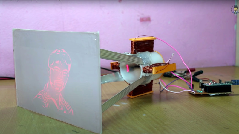
There are some times when an awesome project comes into your feed, but a language barrier intervenes as you try to follow its creator’s description. [Kanti Sharma]’s laser display appears to be a fantastic piece of work, but YouTube’s automatic translations in the video below make so little sense as to leave us Anglophones none the wiser as to what he’s saying. The principle comes across without need for translation though: he’s taken a laser diode module and is using it to create a vector scan by mounting it in the middle of a set of coils driven through beefy FETs by an Arduino. It’s an electromagnetic take on the same principle used in a CRT vector displays such as the famous Vectrex console, with the beam of electrons replaced with laser light.
It’s a technique not unlike what’s been used for years in the lighting industry, in which much larger laser displays are created with mirrors mounted on galvanometers. There must be a physical limit at which the weight of the laser slows down the movement, but if the video is to be believed it’s certainly capable of displaying graphics on a screen.
People have done a lot of things with lasers on these pages, but there have been surprisingly few vector displays using them. Here’s one from nearly a decade ago.


Why don´t you use the spining pentagonal mirror, like barcode readers do???
they’re a bit hard to get ahold of, depending on what part of the world you live. I can get them if I throw money at the problem, but that’s hardly in the spirit of a good hack.
That’d scan horizontally, but what about vertically? Two orthogonal mirrors sync’d so one generates y and the other x? But then you’d be limited to raster and can do vector drawing. By that point you might as well just use a xy galvo setup, but that’s been done to death already. This laser diode deflection is the first time I’ve seen this approach and while there are obvious limitation it’s still pretty interesting to see it working.
*cant, wish I could edit comments lol
TeKaDe’s mirror screw and Baird’s mirror drum provide the answer, both can do a raster with only one moving part, but require extreme precision. They were used in very early TV sets 90 years ago and demonstrated to be workable up to 200 scan lines.
Thanks, I’ll look into those!
Clickbait thumbnail much?
Otherwise cool project, but when videos feel the need to get people to click on them via being dishonest, it kinda taints the whole thing
That’s the first image of his video…
I couldn’t get the CC auto translate to work satisfactorily in the video. But luckily there is enough tech jargon that I could follow along better without CC. This is a super cool project, and it brings back (ancient) memories when I repurposed a CRT with a new circuit to drive the yoke way outside of spec to make a audio frequency X-Y scope for a music demo. (I didn’t have access to a big oscope tube with deflection plates to do it “properly”).
I’m feeling a bit inspired to wind my own yoke now. Thanks for posting this!
Now that’s a real hack, deflecting the light source. No fancy mirrors or drums.
It is a real hack and I would have liked to see the results, sadly he edited in flickering red images. You can see this by going frame by frame whenever he shows the “projection”. (use the keys on youtube to go to the previous or next frame)
Yeah I agree, the result looks fake. Based on the inertia of the laser, the frame rate and image quality appears too high. Each frame also shows a whole image, or nothing, no partial draws even though the laser is visible visible and on.
Yep your exactly right! The image is exactly flickering PERFECTLY every other frame.
What I find the funniest is if you go frame by frame. Even When the Image is off the laser is still on.
I agree the idea is cool. but this seems best categorized as fail of the week.
As the only hack I see here is he hacked the editors here and got on hack-a-day without
any proof it did anything but wiggle.
“DIY Laser Wiggle Machine” <– Kinda like the sound of that.
I do believe it probably would to do Spirography and simple shapes.
Iunno about this one… cool idea, but a end result is a little sus. If you slow down the video to 1/4 speed, the projected images are just blinking and not scanning like you’d expect out of a vector projector. Plus the code he’s provided is a mostly unmodified a copy of a cnc plotter project (B45i/Arduino CNC Plotter.ino) that doesn’t compile or make much sense. Yeah, iunno homie…
But how do you control the movement of the laser module without any magnets?
And why, at the start of the video, does the string of hotmelt glue in front of the laser module move in a weird jerky motion like the video is looped?
Looks fake to me… The laser bounces in the same pattern for the different items that are displayed and if you play the video frame by frame, the laser is on when the image is gone. The image is simply flickered on and off, not drawn by the laser.
The display is foamboard, a poor choice for passing an image from one side to the other. I’m betting the laser is shown on one side while an image is projected on the other side. However, neat concept and I’d like to see what is really drawn by the laser.
I thought the display was a piece of acrylic with paper taped to the back of it, which could work, but I agree that the images do not look like they are produced by the laser being deflected.
It could be. That would make a good easy display. I saw what looked like frayed paper on both sides of the display which is why I thought it was foamboard.
I suspected the same thing.
So out of curiosity, I checked the video desc, and it includes project source code. I downloaded it (warning: 100+MB download, he has all of processing and Inkscape in there) and there is 1 arduino source file.
Put simply, this file is a fraud. Go take a look at it yourself. There’s no include lines, but multiple calls to objects that are never created or defined. Don’t even need to look at it to know it won’t compile. Further, the entirety of the code is just a gcode parser. There’s not a single line of code controlling the electromagnets. There’s even a penUp() and a penDown() function at the bottom, used nowhere. Also a serial print saying “mini plotter is alive”. Also code to *convert to steps per mm for a stepper motor!* It apears this code is just ploter code, with a few lines added in like Laser.delay() to make it look like it’s controlling something.
And this is why I’m weary of youtube *hacker* videos. A lot of it is sensational fluff, to put it nicely. Some is legit, but not all of it by any means.
I watched the beginning of a few of his other videos and looks like this is the case. The schematics are super simplified and cannot possibly work how he demonstrates in the video. Plus there are a lot of odd quick frame edits/cuts noticeable by quick lighting changes that he uses to make it look like it works as implied.
The man is a complete fraud. In another video, he claims to make a “CD recorder” by ripping a Memorex CD drive apart, plugging a microphone to an Arduino’s analog input, and two wires into the CD-ROM drive’s control board.
While he was in the CD ROM drive perhaps he could have taken out the magnetic lens alignment carriage and built a smaller version of the laser projector.
Plus, if you ever waved one of those little pen pointer lasers around, you’d know that it can’t possibly be that bright. It’s less than 5 milliWatts spread over the whole card – you’d need to turn the lights down to see anything at all.
Oh booo!
Somebody may want to run a scanner over the exe files in the project archive, just in case that is the real motivation behind the project, getting people to install something on their windows box. Not saying it is, but I’m just saying it should be checked out.
It”s clear even in the video that the code he’s editing is grbl, a well-known g-code interpreter.
I’ve used stepper motor drives to do some odd things, but he’s only got PWM available. Scanning the frame at something around 50Hz, if the same mechanism can also do lines at a few kHz, isn’t going to go smoothly.
Surely fake. You will not be able to reliably project circle with this setup, if you will be able to project anything at all. There will be more ringing than sensible motion. laser is loosely hold in place with little to no reason to stay roughly in the middle. It does not have any sort of closed loop control, which would be needed for such loose mechanics. Certainly will vastly overshoot positions. These lasers are rather delicate, so you would destroy it relatively soon. Also i don’t see how that laser module made mostly of bronze, copper, glass and epoxy could be attracted by electromagnets (with paper core). This is total trash.
hum… I’m highly skeptical of this approach, and at least a few sections of the video are definitely fake… First, the video thumbnail, there’s BLACK in it, you can’t make it darker than the surface XD
Near the end of the video he “projects” the arduino logo. Pause and look at it frame by frame, it’s blinking on and off complete.
My main doubts is that this thing can do what he wants, at maybe 1 frame every few seconds, and calibration would be hell… The emitter has too much mass to be steered around.
Looking more closely at the version he has working near the beginning of the video, with his profile projected, I’d guess he has a mask with the contour open just under the surface of the plate, and an LED blinking behind it. Else than that, it’s just the emitter randomly vibrating there. I’ll go as far as saying that he probably tried to make it for real, got crap results and then decided to not waste his effort and fake his way through the rest… Though that might be too charitable.
I’m thinking this might be right. Because some of his other projects are a lot more plausible.
But sub in a stiff spring, and a laser diode housing that’s actually magnetic (brass?) and you might be able to make Lissajous figures? Slowly?
Well, the LED there IS moving, though it’s not impossible he just has something vibrating the base of it. It might be a little hard to control with G Code if that’s what’s actually running on that Arduino, but it might be capable of making some neat patterns as-is, even if you might need the lights off to see anything.
Looks fake to me.
Is this april fools or something ?
First thoughts after watching and thinking about the video, practically with such a setup you could probably draw simple shapes but that’s it. Too much mass, overshoot will be horrible. Look at commercial mems laser projection mechanisms like microvision and how much trouble they have with how they have to raster scan in order to compensate the physics of a moving tiny mirror at decent resolution and framerate. I also thought it was weird there’s only four fets, only one full h-bridge or drive two coils with only a half bridge each? I think r4m0n above is correct, the youtuber really did give it a good try to get it working but just couldn’t do so well enough to impress his audience so he fudged the actual image generation on the screen so he could finish the video.
Yes all that plus the electromagnets have very few turns plus a large distance to act on, and the laser assembly has no magnets I could see on it. If you want bi-directional laser movement from the coils the laser assembly has to have a field itself for the magnets to push and pull. Just a piece of iron in the field wouldn’t necessarily even move – or if off center enough may move toward the closest coil but that’s it. Think of a galvo, speaker, or hard drive – you have a coil and a fixed field to work against (or with).
As has already been said – too much is wrong in the video and its clearly faked (projected from the front, flickering, output doesn’t match laser positions etc etc etc).
No need to check the code – there isn’t even any detail on the underside of that board, I suspect it’s not even all soldered up.
The worst part is that the website aims to be educational. No doubt someone will learn a great deal trying to replicate, but will feel duped afterwards and probably angry.
I once used an Arduino mega, to pump out a repeating cycle of ~300 points over PWM pins to some ebay £50 chinese galvos. The results were good, but not as good as this. Let alone animation lol. Thin crisp lines with the occasional blip and bright points at direction changes, not the smooth uniform perfect lines we see here…
As someone else already said, the file with the “sources” include some .exe files… Maybe someone should check them for trojans/viruses, just in case… (I can’t, I use Linux).
Linux user here too. I tried uploading stuff to http://www.virustotal.com but yeah, slow internet and big files… The Inkscape binary seems legit (but old as hell, 2010) as the MD5 (yeah i know) matches the one from the official website. Did not check the other executables. I can’t tell for sure but it looks more like somebody had no clue what he is doing and uploaded a hole shitload of stuff instead of just some code files. As far as i looked there is only FOSS-stuff.
Uh this is handy, you can directly check SHA256 hashes at virustotal. Tested a few of the executables, no match and most of them are “distributed by Oracle”. I don’t think (of course you should not trust me!) this guy is distributing malware, “just” fake stuff. BTW, if you look into some files there is a windows-path with a username that leads to another YT-channel with Arduinory-stuff, not sure how this is related to this guy. I don’t want to spend more time with this.
Frame by frame on the intro is enough to tell you this is fake, come on…
This is unfortunate because if he was serious he would have been able to demonstrate some basic shaky vector graphics, but the natural frequency of a laser diode suspended on some wires like that would greatly limit the amount that could be displayed anyways. He took a teaching opportunity and turned it into a lie.
This article could be a debunking and an intro to why tiny low-inertia mirrors are used for this purpose.
It seems like he’s selling some sort of “engineering education” on his website, and the videos are probably a bait for people to enroll in his bogus courses.
Well that’s a shame.
Oh well (after reading other comments). I wondered if the weight of the laser pointer might not be a little heavy…
This article is a total Joke, fake. If you go tho the project’s page (linked in the YT video) there is only a crude schematic and “downloadable source code” that obviously doesn’t work. (File is around 300 megs!)
I wonder, considering this is effectively a vector display, how much it would take to drop this in place of a monochrome crt and play asteroids.
An other clue that it’s a fake is the shot you see before starting the video. It’s showing at least 3 colors (white, black and red). In the video you see that the laser diode has only two wires, so it’s a single color diode.
There’s no diode that can project black, lol.
Back in the day, I bought a couple of those bare 405 nm laser diodes. The first few batches were very sensitive to static electricity.
I have a few dark-emitting diodes.
All lasers above a certain power can make you see black, if you look at them at the right angle…
Well, that one’s obviously fake, but in 2021, a YouTube thumbnail image that hasn’t been thoroughly photoshopped, or at least not prominently featuring the presenter making that “I’m so shocked” face is a sign of amateur production.
Sigh.
LOL what a scammer. Even the schematic shows N-channel FET’s used as P-channel FET’s Ina way that the Arduino cannot possibly drive. Sigh.
…and also the ground of the coils running through the gnd of the arduino! A reset of the cpu every single pulse at the coils would be guaranteed!
this looks a little more realistic https://m.youtube.com/watch?v=svQdYuvr7dQ
I am having trouble believing this could work as shown. I haven’t worked with galvo’s before but the diy galvo’s shown looks suspect to me.
Very impressive. as complete frauds go. His last job was an official IRS tax collector. Anyway, you might get some basic inaccurate vector shapes out of the contraption, but forget about anything raster.
With an expensive high-end laser galvo, you can get soso vector-game results.
https://www.youtube.com/watch?v=nPzeglKFgMs
my god, the comment section on youtube is as depressing as the whole fake contraption… I’ts almost as bad as all these free energy BS…. O_o
Now that’s clever, is it possible to add RGB? Best would be to demonstrate with star wars console.
This video of the guy also seems very suspicious to me
The beginning with the “THT” oscillo seems very strange to me
https://www.youtube.com/watch?v=_A-SEY_7lxA
I think the gauntlet is laid down…
can any hackers on here actually make a working version?
I think hackers are ROFL
nice idea, clearly fake.
Hackaday, can you put a little disclaimer or warning on things that are faked? The concept is interesting, so has some value here, but this is not an implementation of that concept.
Nooo! Nooo, god NO! Come on! Just fake AF! Seriously, anyone think that badly wound copper wire could lead to those perfectly horizontal and vertical lines? And want to talk about the border of the image: perfectly defined. And the black of the image that is, well, black when the screen is white…
Just wanted to waste a couple of minutes more and checked the arduino sketch and other videos of the guy….These things belong to TikTok. HaD, please do your homework and do some fact checking.
Agreed there’s no way a heavy laser on the end of a wire can do what’s shown, but I’m intrigued…
The support wire is almost definitely steel and electromagnets could attract that using a pull-pull setup rather than the customary push-pull against a magnet, and then the drivers could be single ended not H-bridged. The balance of the wire spring force against the laser-housing and wire weight could be tweaked for different mechanical properties, resonance, and bandwidth, further improved by applying some control theory to the magnet currents, doing path planning based on the mechanical system properties, and operating within small deflection angles. And it still wouldn’t be able to draw the figure in the video I think :-)
It looks like the linear electromagnets act along the entire spring wire length, which reminds me of deflection of the electron beam along the entire length of a CRT tube. The carefully-shaped magnetic deflection coils (rewired for pull-pull) from an old CRT might be a fun place to source coils. Maybe switch to an optical fiber to reduce weight, to which could be glued iron filings to omit the steel wire too. Stick that back into the old CRT bottle and pull a vacuum — a mechanical CRT :-) Ok that’s crazy and the “beam” weighs astronomically more than the original electron beam, so high-frequency response would still be disappointing.
i dont even understand how it even got published to hackaday.. this guys entire channel is either fake or incomplete stuff.