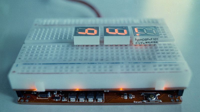
There’s no doubting the utility of the trusty solderless breadboard, but you have to admit they’re less than perfect. They’re not ideal for certain types of circuits, of course, but that’s less of a problem than those jumper wires. The careless will end up with their components hopeless tangled in a rat’s nest of jumpers, while the fastidious will spend far more time making the jumpers neat and tidy than actually prototyping the circuit itself. What to do?
 One way to crack this nut is to make the solderless breadboard jumperless, too. That’s the idea behind “breadWare” a work-in-progress undertaken by [Kevin Santo Cappuccio]. The idea is to adapt a standard breadboard so that connections between arbitrary pairs of common contact strips — plus the power rails — can be made in software. The trick behind this is a matrix of analog CMOS switch chips, specifically the MT8816AP. Each chip’s 128 crosspoint switches can handle up ± 12 volts, so there are plenty of circuits that can use these programmable silicon jumpers.
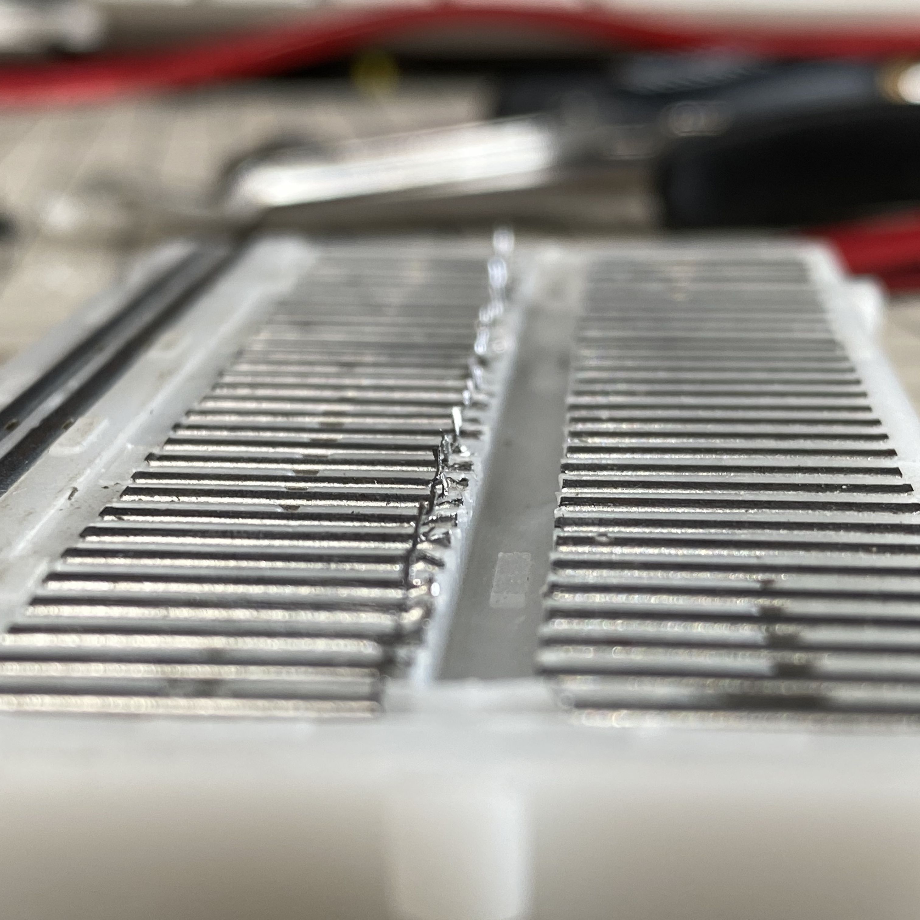
[Kevin] is currently on version 0.2, which is sized to fit under a solderless breadboard and make a compact package. He shared details on how he’s connecting to the breadboard contacts, and it looks like a painful process: pull out the contact, cut a small tab at the gutter-end, and bend it down so it forms a lead for a through-hole in the PCB. It seems like a lot of work, and there must be a better way; [Kevin] is clearly open to suggestions.
While we’ve seen crosspoint switching used to augment solderless breadboarding before, we find this project pleasing in its simplicity. The thought of tossing out all those jumpers is certainly tempting.


That’s a really cool project. A neat addition would be small screens on each side that diagram what connections are currently made.
A touch screen so you could see and draw the connections in real time.
Pogo pins
Or solder a pcb to it
Looks like a CPLD with extra steps
Except you can’t implement 7 segment LED displays or vibration motors or accelerometers or dip switches or any other “fun and interesting” component.
Well is only sharks with lasers that need to drive a 7 Segment with more than 15mA.
15mA (ImaxIO) is enough for any small signal processing and when you need more current you can throw in some bipolars or FETs, after all it’s still a breadboard.
I do something similar with digital.
I have hundreds of old stock Xilinx XL9536XC 5v tolerant, 3.3v Vcc CPLDs. (36 Macroo cell).
When I prototype, I make a single sided surface mount PCB with all the digital chips I need and a splattering of CPLD chips that rout “ALL” the signals between chips. Then just program the connections in VHDL. Then if I make a mistake or need to modify connections, it’s just a change in code.
AKA, the world’s simplest FPGA? This is actually really cool.
It also does analog, so actually a FPAA (Field Programmable Analog Array).
Seems like an idea like this would be cool for one of those analog synths where you plug in all of the cables.
Well, I’ll stop doubting as soon as I meet a breadboard that I trust. With breadboard it’s always a matter of guessing whether it’s your design’s fault or the breadboard’s fault.
Even worse, you have to specifically design for breadboardability, and the stuff that actually needs to be prototyped like switching regs doesn’t work well.
Analog and high speed doesn’t like the parasitics, digital and low speed doesn’t need the handmade proto stage to begin with if you’re careful.
Cool project, but the MT8816AP might be even cooler! Never knew about this little gem.
i’m pretty ignorant about all this stuff but i keep desiring such a kind of switch, and every time i look, i find it’s not really true. you have to carefully match the switch to your actual requirements even for simple circuits. and then you still have to accept a degree of unideal behavior. they’re always either really unity-gain op amps or some sort of transistor that has a voltage bias or resistance or something.
i don’t really understand the underlying technologies and the MT8816 datasheet i found doesn’t have a schematic of how the connection is actually made. but right off (assuming i’m interpretting correctly), i see max current is 15mA and typical on resistance is 45ohm at Vdd=12. it’s certainly an interesting component that could be used for a lot of things but the caveats are huge. dominating, even. i can’t think of a single circuit i’ve breadboarded that it would be amenable to. especially since i use the breadboard as the step before soldering it together…the extremely different behavior of a wire compared to this switch makes it a complete non-starter for me.
if i understood how the circuit works well enough to predict the effect this interconnect would have on it, i wouldn’t need to breadboard in the first place.
For small signals that keep the current low, this should act more or less like an ideal switch. Of course the on resistance will vary between where exactly you are within the voltage range, but you need to be dealing in kilo-ohms anyways and the error of adding +-75 ohm to that should be insignificant to that by design. Otherwise you’re designing a circuit that can’t actually be built because of component tolerances.
(Well, it can, at least once, but your mileage will vary)
yes, once you have this device, you can go out and invent a project that is all small signals where +/-75ohm doesn’t matter. but i’ve never done a project like that. i can’t even think of such a project that would be at this scale. pure digital is almost the only thing that would qualify and for that you either have such a large number of connections that this breadboard is a drop in the bucket, or such a small number of connections that you’d rather just use ic clip jumper cables
This is so much a whole new level.
Add a touch display to make connections in real time and you have a winner.
I can see this as both an educational tool and a development tool.
There’s actually a half finished bit of code in there to put some frequency (or whatever signal) on a probe so you can just poke it into different rows to tell the board which connections you want to make without a computer.
The next step after I get the fundamental stuff working well is to do something like you mentioned. There are a few ways to go about it, I think the slickest way would be to have a display built onto the top of the breadboard, but making a display with that many holes in it would probably take Samsung levels of development. The other way is to have a pico projector and a camera mounted above, but everything I’ve used that tries to do something like that is too slow and buggy to be useful and all around is just an absolute dumpster fire.
Not saying either of those things can’t be done, I just need to come up with a way to do it that doesn’t detract from the experience.
If you have any ideas for an elegant way to do that, I’d love to hear them.
I love the probe idea. For indication, an rgb led per column, and each ‘net’ made given its own color code.
Not as slick as an overhead projector for certain, but easier to drive a ws281* strip.
Although in my experience those off-brand off the shelf clear plastic boards were crap, merging a clear case with bb830 clips sounds easier than the display with holes in it idea. Opens more led placement options.
But even plopping leds above and below the board isn’t too horrible of an idea (except for the power rails being a little in the way)
I do like the idea and have to have a closer look at the chip.
I had been looking at something similar – but for digital only.
Each pin should have
– Programmable resistor to plus
– Programmable resistor to ground
– Set as Input
– Set as Output
– Set as Tristate
All as a shift register block per pin, so software programmable.
But until now could not find a suitable FPGA / CPLD,
For a breadboard the system should cover at least 60 pins 30+30.
As it is all based on shift registers it can be expanded easily.
And all controlled by software.
Well, here’s a suggestion: Castellations to solder a PCB directly to the strip.
I’m brand new to Arduino. After two weeks working with a breadboard, I wondered how to create a breadboard where the pins are assignable. Even better would be a breadboard that could “feel” where pins are inserted.