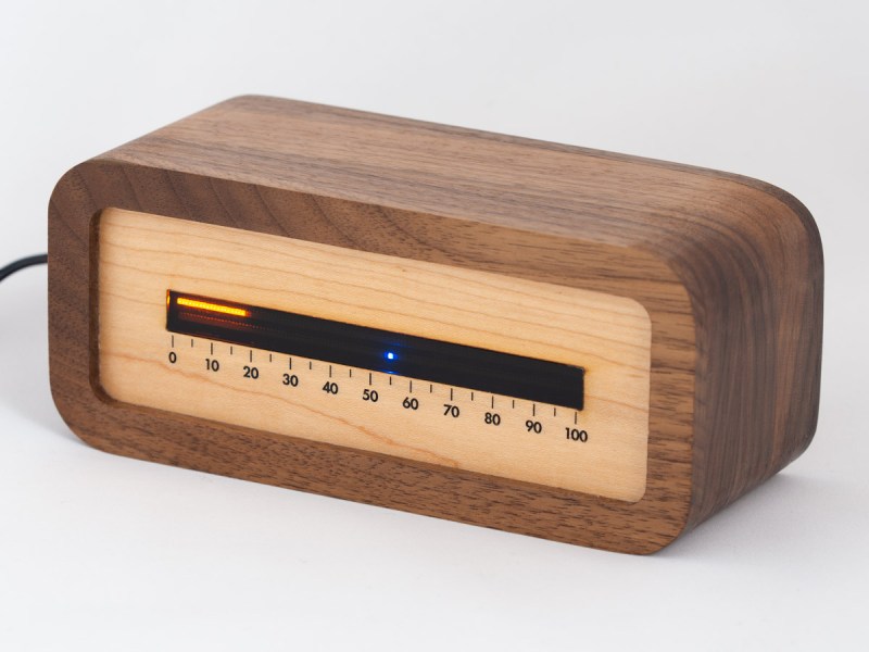
The notion of segmenting and quantizing the day into discrete segments of time is perhaps one of the most human things we do. Heralding back to a simpler era when a day was just a progression of sunrise to sunset, [James Wilson] created a beautiful linear clock that shows time as progress throughout the day.
For previous projects, [James] had used nixie tubes but the headache of the inverters, high voltages, and tight spaces led him to instead use mini-LED’s. Two PCBs were manufactured, one as the display and one to hold the GNSS module as it works best when mounted horizontally to point at the sky. Two rows of 112 tightly packed LEDs make a great stand-in for bar graph style tubes and are are controlled by TLC5926 shift registers. The venerable STM32G0 was chosen as the microcontroller to power the clock. With the help of some approximating functions and the location provided by the GNSS module [James] had the position of the sun which he then could turn into a % of progress through the sky.
The enclosure was modeled after the mid-century modern look and made of several pieces of wood CNC’d and then glued together. Machining it out of a solid piece of wood would have been difficult as finding long enough end mills that could carve out the interior is tricky. We think the resulting clock looks wonderful and the walnut accents the maple nicely.
The writeup is highly detailed and we love the honest explanations of what choices were made and why. The code is available on GitHub. Or if perhaps you’d rather eschew the LED’s and go for something more physical there’s always this ratcheting linear clock to draw inspiration from.


Very nice looking, he should add a thermometer function, red for C+ and blue for C- (well I’m assuming outside temp.)
Better directly upgrade to C++
i had no internet for a month and just for something to do i built a binary clock out of chained half-adders, just 20 bits (one LED per bit) incremented every 2^20th of a day, so if it was a number it was counting from 0 at midnight to 1048575 just before midnight the next night. i knew that would not be a very useful timekeeping method, but whatever. this idea of measuring a fraction of the sunlit part of the day seems much more interesting!
when i was done, i was gonna go to a frame maker (like for paintings or whatever) to get a nice wood and glass frame made for it. but i used a 555 for timing and from the first moment, i could tell, it was not a usable timepiece because of that poor decision. i lost interest. later when i got a basement i set in down there as a nightlight, unsynced with any time standard.
why not just use a 555, they said.
Yeah, personally the 555 is overrated to me. Sure, it’s great at the myriad of things it can do, but if you have an MCU in your design with spare pins and capability then why not use it, rather than being a hipster looking for a reason to use a 555?
You use a 555 when you need continuously variable timing, smooth ramps, and to free up the MCU to do other things than just toggle a pin at a set rate, which isn’t precise if you want to run any other interrupt at the same time.
Why even use a 555, just when a brushed DC motor would do, as long as you keep the voltage constant?
0-100 for time? WTF?
Then you’d hate how I look at calendar time:
If the year is a day, each month is about 2 hours, so right now it’s a little past noon.
You’d hate how I look at calendar time: each year is represented by a narrow gauss curve shape that centers around new year and the negative two sigma is around September, while positive two sigma is around May, so the months are compressed differently going up the slope than down the other side while the shape of the year stays symmetric. The color of the year at the top is red and the bottom of the curve it’s white. Each summer between June-August is about as long as the year is high.
I do not know what this means.
Did you ever wonder, how long time didn’t exist for, before it did?
No, but I’ve considered what it would be like to go sideways in time.
I think you might enjoy Greg Egan. If you want to start with one of his most challenging (in terms of the physics…), your passage here reminds me of Dichronauts, which comes with a quite-detailed explanation of the physics: https://www.gregegan.net/DICHRONAUTS/00/DPDM.html
Meet me in the town square, 50. Bring your pistols.
That wood case is absolutely beautiful.
+1
Yeah, came here hoping for more info. There is some on his website but I think the “photo” is actually a render, because he cut several layers and glued them together but there are no visible seams or mismatched grain in that image.
I’d like to see a good tutorial on making this kind of enclosure. How to do the CAD and then get it milled (by a service provider, I don’t have a CNC milling machine). If that is a photo then how do you get it perfectly aligned for gluing and hide the cuts?
Imho it’s definitely a photo, looking at details like a bit of white glue where the frame meets the front plate and stuff like the laser cut edges…
Actually yeah I see it now, the grain doesn’t match up perfectly either so you can see where the layers are stacked.
> If that is a photo then how do you get it perfectly aligned for gluing and hide the cuts?
Glue them together using K-style parallel clamps, then follow up with sanding all around. Any remaining tiny holes and gaps can be filled with wood putty and sanded. I could even make things more foolprool by milling tongue-and-groove slots between the sections but found working carefully during glue-up was sufficient.
nice work on the wooden case but would have been even cooler if the linear lines where made out of colored ribbons moving on pulleys like in the old radio! better still the whole thing was mechanical with just one motor taking care of the belts and pulleys ! :)
nice but why wired? we have 21 century
50Hz or 60Hz from the mains is still more precise than what you would get with a crystal, even though that has it’s own problems as well. You could calibrate the crystal clock, but I’d expect still to loose something like 1 second a month or so.
Also, I believe that such a Nixie bargraph uses something like 10mA at 120V, which is still 1.2W. A normal AA battery is about 2000mAH, at 1.2V is about 1666WH. Which means you would have to put in new batteries every about 80 days.
These calculation are very rough estimates of course. But you get the gist, I think.
Ummm.. 2×112 LEDs. That is all.