Hackers love the warm glow of a vacuum fluorescent display (VFD), and there’s no shortage of dead consumer electronics from which they can be pulled to keep our collective parts bins nicely stocked. Unfortunately, figuring out how to actually drive these salvaged modules can be tricky. But thanks to the efforts of [Lauri Pirttiaho], we now have a wealth of information about a VFD-equipped front panel used in several models of Topfield personal video recorders.
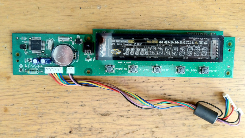
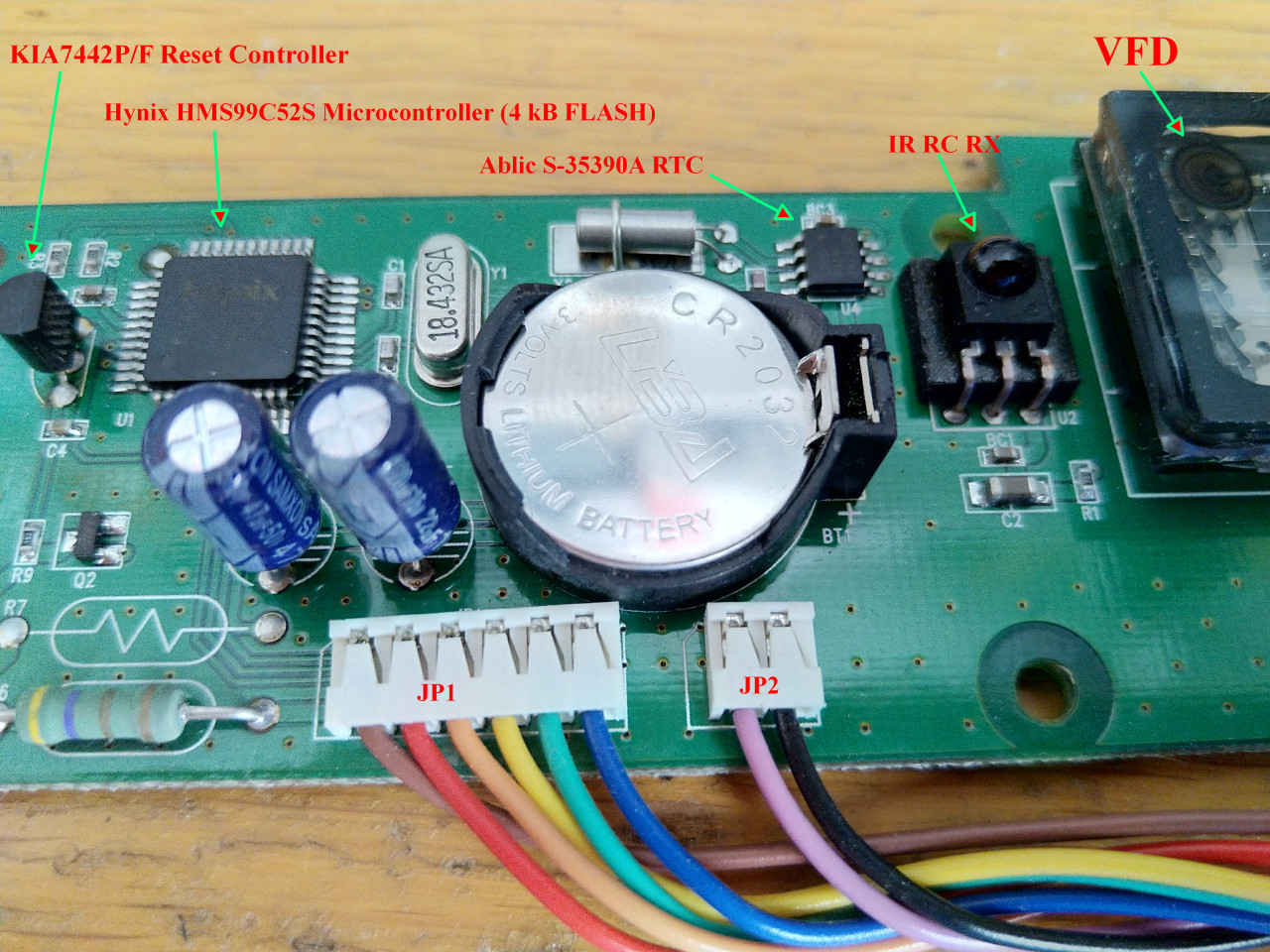
The board in question is powered by a Hynix HMS99C52S microcontroller and includes five buttons, a small four character 14-segment display, a larger eight character field, and an array of media-playback related icons. There’s also a real-time clock module onboard, as well as an IR receiver. [Lauri] tells us this same board is used in at least a half-dozen Topfield models, which should make it relatively easy to track one down.
 After determining what goes where in the 6-pin connector that links the module with the recorder, a bit of poking with a logic analyzer revealed that they communicate over UART. With the commands decoded, [Lauri] was able to write a simple Python tool that lets you drive the front panel with nothing more exotic than a USB-to-serial adapter. Though keep in mind, you’ll need to provide 17 VDC on the appropriate pin of the connector to fire up the VFD.
What’s that? You don’t need the whole front panel, and just want to pull the VFD itself off the board? Not a problem. Our man [Lauri] was kind enough to document how data is passed from the Hynix microcontroller to the display itself; critical information should you want to liberate the screen from its PVR trappings.
If you manage to get your hands on one of these modules, it would be an ideal addition to a custom media streamer. Though we suppose simply turning it into a network-controlled clock would be a suitable alternative if you’re looking for something a bit easier.


Mike S. featured a story on Dave Jones reverse engineering work on VFD’s back 6 years ago: https://hackaday.com/2015/03/04/reverse-engineer-a-vfd-after-exploring-how-they-work/
These standard modules that are often used in expensive pro equipment, like the 2×40 Babcock module in Dave’s video, are somewhat easier to “reverse”. Even if you don’t find anything on the particular one, usually the datasheets for some modules of the same family (like Babcock VF-0140 which is 1×40 with the same parallel interface), or for compatible ones (some Vishay Dale modules), are available.
Custom modules pulled from mass products are bit more challenging, in particular when not even a service manual can’t be found. Poking with an oscilloscope, like in the Dave’s video, is a way to start, but one must have the device-to-be-salvaged still in the original equipment for that. That means, if you want to re-use something, before destroying the world around it, take a look if you can find manuals/datasheets. If not, start the inspection before disassembling the equipment totally.
The first step is to recognize/document the digital, analog, and power/ground wires and pins from the live equipment. The next for the digital interfaces is to use logic analyzer, memory scope, data logger, or often just a dev board like Arduino, ST-Nucleo, etc. (my favorite is Cypress CY8KIT-049) to record live sequences of the digital signals. Then comes the hard part of first recognizing/guessing what the signals are, and then verifying that the guesses are correct, by writing test drivers. For serial/SPI/I2C one can use a PC with a usb/serial dongle, and something easy like Python in this study. For parallel protocols a good choice is to use a dev board and some user-friendly IDE like Arduino in the Dave’s video.