We think of radio navigation and direction finding as something fairly modern. However, it might surprise you that direction finding is nearly as old as radio itself. In 1888, Heinrich Hertz noted that signals were strongest when in one orientation of a loop antenna and weakest 90 degrees rotated. By 1900, experimenters noted dipoles exhibit similar behavior and it wasn’t long before antennas were made to rotate to either maximize signal or locate the transmitter.
Of course, there is one problem. You can’t actually tell which side of the antenna is pointing to the signal with a loop or a dipole. So if the antenna is pointing north, the signal might be to the north but it could also be to the south. Still, in some cases that’s enough information.
John Stone patented a system like this in 1901. Well-known radio experimenter Lee De Forest also had a novel system in 1904. These systems all suffered from a variety of issues. At shortwave frequencies, multipath propagation can confuse the receiver and while longwave signals need very large antennas. Most of the antennas moved, but some — like one by Marconi — used multiple elements and a switch.
However, there are special cases where these limitations are acceptable. For example, when Pan Am needed to navigate airplanes over the ocean in the 1930s, Hugo Leuteritz who had worked at RCA before Pan Am, used a loop antenna at the airport to locate a transmitter on the plane. Since you knew which side of the antenna the airplane must be on, the bidirectional detection wasn’t a problem.
Basic Navigation
Radio navigation owes a lot to ordinary celestial navigation and surveying. Instead of sighting a lighthouse, the sun, or a star, you sight a radio transmitter.

Consider you are in a field that has a flagpole on it and you know the exact location and height of the pole. If you are somewhere in the field and want to know where you are, you can use the pole. You sight the pole and measure the angle to the pole. Since you know the height and the angle, you can use geometry to draw a circle around the pole that you must be on.
Of course, you could be anywhere on the circle — what navigators call a line of position. But what if you had two poles? You could draw two circles. If you are lucky, the circles will touch at exactly one point and that is where you are. However, it is more common to have two points and — presumably — one will be very far away from where you ought to be and one will be close to where you should be.
Even with a simple pair of loops, you can do the same trick if they are far enough apart. If station one shows an angle of 30 degrees (or 210 degrees; it is ambiguous) to the transmitter and station two shows an angle of 300 degrees, you can triangulate by drawing two lines and noting where they cross.
Improvements
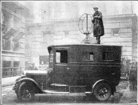
Even so, there was a demand for something better. In 1909 Ettore Bellini and Alessandro Tosi introduced an innovation. The Bellini-Tosi system used two antennas at right angles that fed coils. A third loop moved inside the coils to find the direction. This allowed the large antennas to remain stationary. By the 1920s these were quite common and remained so until the 1950s.
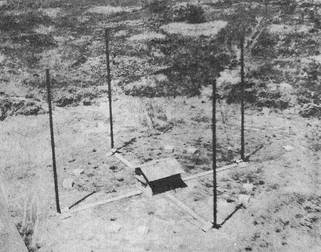
By 1919, the British engineer Frank Adcock came up with a system that used four vertical antennas, either monopoles or dipoles. This arrangement wired the antennas to effectively make a square loop that ignores horizontally polarized signals, thus reducing the reception of skywaves. Adcock antennas were often used with Bellini-Tosi detectors.
Lightning Strikes
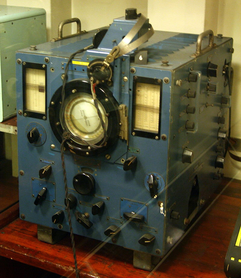
In 1926, Brit Robert Watson-Watt was trying to detect lightning to help airmen and sailors avoid storms. Lightning signals are very fast, but it took about a minute for an experienced operator to line up a Bellini-Tosi detector. By coupling an Adcock antenna and an oscilloscope, Watt was able to rapidly lock onto a lightning bolt or a radio transmitter.
The military high-frequency direction finder or huff-duff proved invaluable during the war. The German U boats kept transmissions short to avoid detection, but with the huff-duff, that didn’t matter. The Germans didn’t figure out the technology improvement and estimates are that 25% of U boat sinking were due to the huff-duff.
Modern Times
Modern-day systems are much more sophisticated using phase locked loops and other techniques. Although some early systems like the one used by Pan Am used transmitters on the plane and receivers on the ground, most systems do the opposite. Older ADF — automatic direction finding — sets used motorized antennas to locate known transmitters. Modern sets use the Marconi system with multiple antennas, although the switch is electronic in this case.
Ham radio operators enjoy fox hunting — part of the event known as “radiosport” in most of the world — which is essentially hide and seek played with a radio transmitter. You can see more in the video below.
You might think that GPS has made radio direction finding a thing of the past. However, if you think about it, GPS is sort of a different form of radio direction finding. Instead of using a bearing of an antenna, you are measuring signal arrival time, but it is the same idea. The time delay gives you a circle from the known position of the satellite. Making multiple circles around multiple satellites gives you an exact position.
Sure, the technology is a far cry from Hertz’s loop antenna. But radio direction is still a key part of modern navigation systems.


That’s Uruguay, friend, not Paraguay.
No it’s not.
From the Wikipedia article that image is from:
“In this case the navigator is either located on the Atlantic Ocean, about 350 nautical miles (650 km) west of Madeira, or in South America, about 90 nautical miles (170 km) southwest of Asunción, Paraguay.”
*guay
Sorry, the circles intersect over Paraguay and Argentina. Uruguay is a little east south bound.
During the 2016 Democratic convention I was working in one of the tents for my company that was broadcasting the event. The Sunday before the event began the Radio guy from the FCC showed up in my workspace and was tracking down interference from what he assumed was my equipment. I had just started a show, so I asked him if they could wait for diagnostics. Thankfully they could.
After the show we powered down, removed all possible sources of radio waves, removed all cabling….everything the guy asked me to do (we are there and allowed to broadcast with the understanding these guys can shut us down, I was very cooperative.) Still the interference was present.
I asked him where the main antenna was that they were using to determine I was interfering. He told me and showed me the spectrum. Yup, a strong carrier was up and in the direction of my equipment. He was using portable gear to determine where the signal originated.
I stood my ground “my gear is off, my cables are completely disconnected…if this interference is me I want to patent the perpetual motion machine I must have created.” The guy agreed and began looking elsewhere.
Where was the FM signal coming from? From the fancy Port O’Johns located 250 feet behind my tent on exactly a straight line between me and the receive antenna reporting the interference. They had music playing inside apparently from wireless speakers.
He apologized profusely. I accepted the apology and got to work taking 4 hours to reassemble and test my equipment before I could go back to the hotel. Later his supervisor stopped by and also apologized. Again I was nice, but mentioned “once I powered down my equipment if you didn’t see a change in the carrier level, this guy should have looked elsewhere.” He agreed and apologized again. I let it go, we were all tired and it was crunch time. Mistakes happen.
Moral of the story – verify your findings. Look for sidelobes. Stretch out your search zone and VERIFY you have the right source before asking anyone to do destructive changes to fix an issue.
Next time I’m standing my ground sooner. Professional courtesy or not, that was totally avoidable.
Wow, what a day! I agree with you, though.
I had the same experience. Except I was the finger pointing guy that was hunting down an offensive RF signal that swamped my home. I initially blamed the wrong transmitter owner, and after realizing my mistake, I offered my apologizes.
So here’s a story told from the other side of the fence:
One summer morning my home security alarm, sprinkler system rain detector, and backyard weather station went offline. Hoping the issue would go away on its own, I waited until the next day before I began an investigation.
My bench top HP 8595E network analyzer found a strong continuous RF carrier on 433MHz. Which is the same frequency used by the disabled devices.
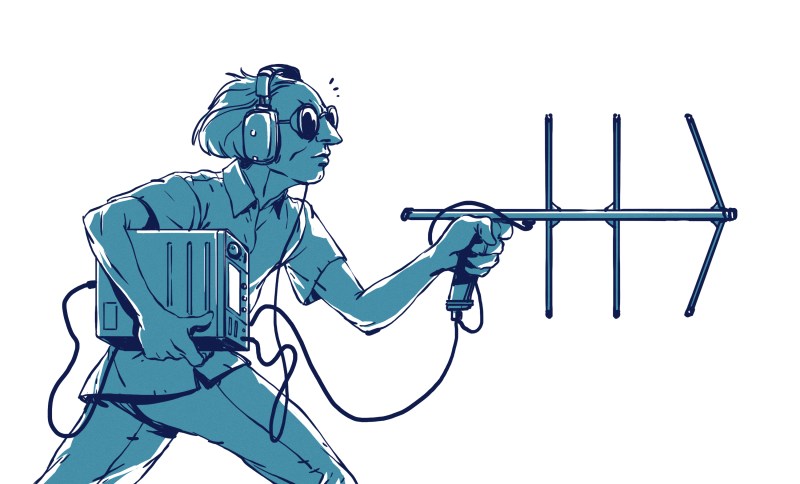
To go mobile I built a directional antenna (433MHz Yagi) and installed SDR Sharp (SDR#) on a handheld Android tablet. SDR# is a receiver app that is popular with ham operators and RF experimenters. Good for fox hunting too.
Triangulation found the culprit; A huge city owned water tank that was several hundred feet from my home.
I could see an antenna on the top of the water tank pointing at my house. It was a Yagi with element lengths suitable for 433MHz. Bingo, or so I thought.
After a phone call to the city, a water district worker stopped by my home and I showed him my findings. He didn’t grasp the concept of fox hunting and told me that the city wouldn’t do anything about my problem. So he drove off. This was day #3 and all my RF devices were still offline.
The next morning I decided to triple check my fox hunting. As before, I was led to the water tank. But this time I also found the same signal coming from a nearby HV power line tower. At the top was a cellular antenna installation.
Careful observation found that the water tank was reflecting the 433MHz RF signal from the cellular installation. Later that night I found the emergency phone number at the antenna site. It was posted on a Cingular PCS labeled cabinet. I called them at 9PM. A woman answered, listened to my story, and within twenty minutes of ending the call the problem was fixed.
The next day I called the city, found the water district worker I had spoken to, and apologized. As before, he didn’t have much interest talking to me, but I felt better for trying to right my wrong.
We all make mistakes. How it is handled makes a difference. Remain civil / professional and everyone has the opportunity to part ways without a lot of drama.
And then there is the case where you are the offender yourself…
At the time, years ago, I was living with my friend in his house.
I was working on a small transmitter on 433MHz. Couldn’t get it to work, didn’t get anything on the receive side.
At some point I am tired of working so we decide to go to the shops. Woops, he can’t get his house alarm armed. Luckily I realized that it must be my transmitted causing it without too much head scratching. Woops!
Regardless of why it happened, it also taught me to never leave half working projects live if there is no reason for it.
One day I moved from an apartment to a small ranch home. I had all kinds of ham gear in boxes and recently acquired a 19 foot vhf/uhf antenna. I was excited to put up a packet radio station. I was at a location with excellent elevation. I bolted the vertical to the top of my kids heavy wooden swing set.
About 2 weeks later, my neighbor, a volunteer firefighter, knocked on my door. “Your radio is interfering with my firefighting equipment, and you better turn it off. ” His fire radio, a Motorola handi talkie worked fine. But when he put the radio in the amplified base, (which had a pre-amp and rf amplifier), he bettor hearing interfering voices.
I then told my neighbor, he was an amazing detective to determine I had ham radio equipment. However, I told him that it was hard to believe since my radios were all still in moving boxes and have never been powered on in that house. I explained I only put up the antenna with hopes off one day setting up my station.
Listening to the voices on my neighbors radio, we were able to determine 2 things. First, the voices were that of CBers, in trucks on the nearby interstate, running illegal linear amps, (according to what they said). Secondly, the amplified, drop in base of my neighbors radio had an amplifier and was detecting and amplifying the CBers signal.
It’s easy to jump to conclusions.
We are always taught, and experience teaches that you must scan/drive/pan past the strongest signal and keep going until significantly weaker. Once sidelobes and lesser peaks are observed and ruled out, go back to the strongest. When using directional antennas, naturally, getting more than one angle is key. And even with multipath, simple signal strength methods will lead towards the source.
I was once on orders to find a suspected ELT on the old 121.5 MHz in a dense urban city. Driving through the neighborhood I was told was the area the ELT was in. Really didn’t find much…. but I did find a wavering “dead carrier” almost exactly on 121.5 MHz on one street… visible for a couple hundred feet. Could it be the ELT battery was dying and in it’s last gasp? I had my doubts, but was instructed to find and terminate! It was 02h00 (yeah, people were sleeping). Well… I made darn sure I was going to wake up the correct house. Simple signal strength methods carrying around an IFR1200 with a whip antenna. The homeowner answered the door with a machetes. He could see my gov’t car on the street. He wasn’t a boat or aircraft owner… Hmmm… better find what I came looking for…. did a circuit breaker on off test. … last breaker killed the dead carrier… traced it to a 4 transistor clock radio on which the analog tuning dial was at about 110 MHz. High side IF, so +10.7MHz and we are at 121.5! Told him not to use that radio… being seen by a satellite overhead and is causing issues. He was freaked out. This wasn’t the ELT… but it was on the forbidden 121.5… True story!
A retired FCC agent noted, when I asked, that his team would circle around a reported source and slowly decrease the circle size like spiraling into the source.
Then if the FBI had to get involved, they’d high tail it out of there before those guys showed once they found the source.
Hilarious was, the retired agent noted they’d drink beers and hunt for sources like it was the thing to do. I forgot to ask if was due to boredom or blending in. I was under the impression to make the day go by easier.
Sure as heck looks like Paraguay to me.
antenna searches
retriever’s nose in the wind
ether’s far secrets
Oh, I see someone read Cryptonomicon :)
That was pretty quick. I suspect that two people might find it even quicker.
He didn’t say if he had maxed out his S-meter when he got close.
He did say that he had inserted max attenuation (100db) and was getting about S5 (roughly half scale)…
There is another type of direction finding. You can take an antenna and spin it in a circular moment. This will create a Doppler effect such that the signal you are tracking increases in frequency as the moving antenna goes toward the signal and lower in frequency as it moves away from the source.
that’s a great idea. Or virtually “spin” it with a phased array…
My favorite DF trick, works even with omnidirectional antennas: hold radio/antenna in front of yourself and turn around with the radio. When the signal is weakest, your back is facing it.
Works best when your body width is big relative to the wavelength in question, so VHF or more. Works absolutely brilliantly with 2.4 GHz b/c we’re sacks full of water. Multipath wrecks it, naturally.
The best part? You always have the requisite gear with you — your body and a radio. Helped me pull an RC plane out of a tall wheat field a couple months ago.
We are “bloated sacs of protoplasm”.
My brain is still melted from watching that show…
I did similar for my first fox hunt and still has utility without a doubt. For the first hunt, I started off going towards the hill the signal was reflecting off of and was stuck for maybe a minute or three wondering WTF regarding the reflection?
Anyways… when you get close; you can remove the antenna, place the antenna in a metal can made for the receiver and check out a second or third harmonic depending on your receiver capabilities.
This is my metal can (NIDO powdered milk) where I cut a 325 mesh stainless steel screen out to just fit inside the lid so the can was for the most part sealed and a crappy Faraday Cage.
https://www.facebook.com/james.analytic/posts/2874014875993629
Typo: Replace “…place the antenna in a metal can…” with “…place the receiver in a metal can…”
Also, In regards to “made for” I’m referring to something to help keep your receiver from moving around. I just use some shop rags/towels.
I used this technique with a 2M handheld radio that could receive out of band to hone in on a transmitter that a Lo-Jack salesman hid a few miles away. He was rather surprised but this was in a rural area — not too many streets to hide on but the close-in-body technique on the VHF receiver gave me a general direction to search.
The article fails to mention two of the most useful modern techniques: correlative interferometry and superresolution.
How does an oscilloscope help you find a signal source after it has stopped?
Long persistence luminophore in it. Some CRTs stay lit up pretty long.
I started a project on github called radio-mapper (https://github.com/physiii/radio-mapper)
The objective is to setup a cluster of raspberry pi + sdr devices across the city recording iq values for certain frequency ranges.
I found really good references for triangulation of radio sources using time difference of arrival (using a reference source for syncing). They used a pi+sdr and some random branch of rtlsdr to get real time switching from sync source to source of interest. And triangulated sources with just three pi+sdr’s (I want to have way more capture sources).
Then I can have a public website that aggregates higher level data (processed/trimmed down iq data) to give you a google map location of radio sources.
:)
Awesome idea! There’s nothing in the repo though :) I’d definitely be willing to contribute
Just pushed links to research and boiler plate code to start from. Also got the domain https://radio-mapper.org – Message me on google chat (physiphile@gmail.com)
The *only* way this is going to work well is if you A) strip the OS down to the bare minimum, B) run a real time kernel, C) fit each pi with a VERY stable and accurate disciplined time reference, D) clock the SDR from said time reference. NTP isn’t going to cut it. At best, NTP has an accuracy of ~1mS on a closed and quiet wired network. That translates to location accuracy of +/- 300,000km. It’s 10x worse over the internet.
Assuming your hardware and the underlying network connecting the PIs supports it, PTP boasts an accuracy of 100nS, which if everything is working correctly, would result in an location accuracy of 30 meters. That requires a *closed* wired network. It’s not going to work over the internet.
Time of arrival direction finding is a simple concept, and a high technical hurdle to implement in practice.
B) I would like to see around 100 meter accuracy and I think that is achievable because someone has already shown results here: https://www.youtube.com/watch?v=Km4TU17b05s – There would be a benefit in using a RTOS but that involves a lot more tinkering to get all the bits of software working….how to get some dependency of a dependency compiled to get a particular program installed that is needed by other programs that need dependency tree’s compiled an installed. So yeah I see trying that at some point but not right now.
C & D) I was assuming there would be a reference broadcast signal for synchronization. I would like to be able to do it with a real-time clock as well but like you said that’s a difficult problem to solve.
Can a time standard signal be used? Considering location and propagation characteristics to adjust for any transmission path adulterations?
Maybe some method like this also:
https://www.nist.gov/pml/time-and-frequency-division/time-services/one-way-gps-time-transfer
GPS (https://gssc.esa.int/navipedia/index.php/Time_References_in_GNSS), NIST (https://www.nist.gov/pml/time-and-frequency-division/time-services), etc.
I’m not quite thinking at the time being, though can you note the math logic used for the timing/sync to get the location accuracy result please and thanks you?
I’ve seen 1uS accuracy with GPS on a Raspberry Pi. That equates to 300 meters of uncertainty so not as good as referencing a broadcast signal but of course I would rather not have to rely on a reference source.
The logic for time syncing is as follows: Imagine you and atleast 3 friends are floating a calm pond. Your eyes are closed but you now the position of your friends. One friend (sync) creates ripples in the water that you pick up as movement in your body. Then a source at an unknown location starts creating ripples. As soon as you feel the unknown source you record the position of your body due to your friend’s (sync) ripple. Your friends also write down their bodies position when experiencing the unknown source. Assuming you and your friends are not equidistant from (sync), you can use that phase information infer the unknown source using geometry.
Much easier said than done. My first step is to replicate the results I posted above.
For the Europeans out there, IARU R1 (Europe, Africa, Middle east) Amateur radio direction finding championships will start ending this week, in Bansko, Bulgaria. With all Covid 19 measures.