In today’s episode of “AI Is Why We Can’t Have Nice Things,” we feature the Hertz Corporation and its new AI-powered rental car damage scanners. Gone are the days when an overworked human in a snappy windbreaker would give your rental return a once-over with the old Mark Ones to make sure you hadn’t messed the car up too badly. Instead, Hertz is fielding up to 100 of these “MRI scanners for cars.” The “damage discovery tool” uses cameras to capture images of the car and compares them to a model that’s apparently been trained on nothing but showroom cars. Redditors who’ve had the displeasure of being subjected to this thing report being charged egregiously high damage fees for non-existent damage. To add insult to injury, if renters want to appeal those charges, they have to argue with a chatbot first, one that offers no path to speaking with a human. While this is likely to be quite a tidy profit center for Hertz, their customers still have a vote here, and backlash will likely lead the company to adjust the model to be a bit more lenient, if not outright scrapping the system.
hertz3 Articles
Clock Runs Computer In Slow-Motion
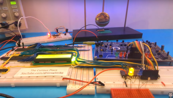
At the heart of all computers is a clock, a dedicated timepiece ensuring that all of the parts of the computer are synchronized and can work together to execute the instructions that the computer receives. Clock speeds for most modern off-the-shelf computers and smartphones operate around a billion cycles per second, and even clocks that tick at a human-dizzying speed of a million times per second have been around since at least the 1970s. But there’s no reason a computer can’t run at a much slower speed, as [Greg] demonstrates in this video where he slows down a 6502 processor to a single clock cycle per second.
To reduce the clock speed from the megahertz range down to a single hertz or single clock cycle per second, [Greg] is using the pendulum from an actual clock. He attaches a small magnet to the bottom of the pendulum which is counted by a sensor as it swings past. Feeding that pulse into a monostable conditioner yields a clock signal which is usable for one of his 6502-based computers, and at this extremely slow rate, it’s possible to see the operation of a lot of the computers’ inner workings a step at a time. In fact, he optimized the computer’s operation as this slow speed let him see some inefficiencies in the program he was running.
It helps if your processor is static, of course. Older CPUs with dynamic storage for registers and some with limited-range PLLs would not work with this technique. The 8080A, for example, required a clock of at least 500 kHz.
Not only can this computer use a pendulum clock as the basis for its internal clock, but [Greg] also rigged up a mechanism to use a heartbeat. Getting in a little bit of exercise to increase his heart rate first will noticeably increase the computer’s speed. And, if you’re looking to get a deeper glimpse into the inner workings of a computer, we’d recommend looking at one which forgoes transistors in favor of relays.
Where’s That Radio? A Brief History Of Direction Finding
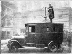
We think of radio navigation and direction finding as something fairly modern. However, it might surprise you that direction finding is nearly as old as radio itself. In 1888, Heinrich Hertz noted that signals were strongest when in one orientation of a loop antenna and weakest 90 degrees rotated. By 1900, experimenters noted dipoles exhibit similar behavior and it wasn’t long before antennas were made to rotate to either maximize signal or locate the transmitter.

Of course, there is one problem. You can’t actually tell which side of the antenna is pointing to the signal with a loop or a dipole. So if the antenna is pointing north, the signal might be to the north but it could also be to the south. Still, in some cases that’s enough information.
John Stone patented a system like this in 1901. Well-known radio experimenter Lee De Forest also had a novel system in 1904. These systems all suffered from a variety of issues. At shortwave frequencies, multipath propagation can confuse the receiver and while longwave signals need very large antennas. Most of the antennas moved, but some — like one by Marconi — used multiple elements and a switch.
However, there are special cases where these limitations are acceptable. For example, when Pan Am needed to navigate airplanes over the ocean in the 1930s, Hugo Leuteritz who had worked at RCA before Pan Am, used a loop antenna at the airport to locate a transmitter on the plane. Since you knew which side of the antenna the airplane must be on, the bidirectional detection wasn’t a problem.
Continue reading “Where’s That Radio? A Brief History Of Direction Finding”


