
3D printers have come a long way over the past several years, but the process of bed leveling remains a pain point. Let’s take a look at the different ways the problem has been tackled, and whether recent developments have succeeded in automating away the hassle.
Bed leveling and first layer calibration tends to trip up novices because getting it right requires experience and judgment calls, and getting it wrong means failed prints. These are things 3D printer operators learn to handle with time and experience, but they are still largely manual processes that are often discussed in ways that sound more like an art than anything else. Little wonder that there have been plenty of attempts to simplify the whole process.
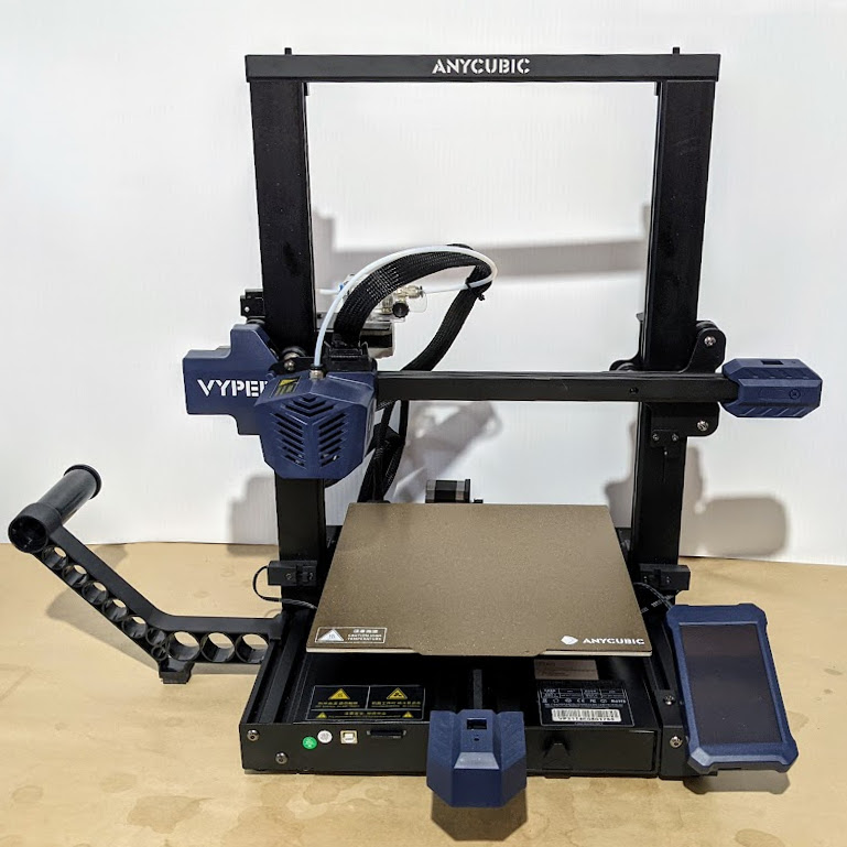
Some consumer 3D printers are taking a new approach to bed leveling and first layer calibration, and one of those printers is the Anycubic Vyper, which offers a one-touch solution for novices and experienced users alike. We accepted Anycubic’s offer of a sample printer specifically to examine this new leveling approach, so let’s take a look at the latest in trying to automate away the sometimes stubborn task of 3D printer bed leveling.
Why is Bed Leveling an Issue?
In 3D printer terms, bed leveling (or simply “leveling”) is a broad term for a process whose end result is getting the first layer of a print deposited optimally onto the build platform. A good first layer is the foundation of a successful print.
To accomplish this, the nozzle needs to remain a constant distance from the build platform across its whole range of movement. If the nozzle is too close to the bed in some places, but too far away in others, that leads to poor quality and failures. Adjusting the printer’s bed until it is parallel to the nozzle’s range of motion is called leveling. (Machinists would correctly call the process tramming, because nothing actually has to be perpendicular to the earth’s gravitational field.)
The next step is first layer calibration. This adjusts the Z-axis offset, or the distance between the tip of the nozzle and the surface of the build platform. There needs to be just enough space for the critical first layer of plastic to be deposited evenly, in a uniform thickness, and pressed into the build surface well enough to remain stuck during printing.
Complicating this is the fact that no build platform is perfectly flat. When fractions of a millimeter count, even small imperfections cause problems. High spots or low spots in a build platform are problems because no amount of tilting the print bed will adjust them away. This is one of the reasons leveling problems have persisted over time.
No individual part of bed leveling is particularly complicated, but the many interconnected factors can make it a complex, fiddly task. It’s no surprise that people have tried different ways to make the whole process as easy and repeatable as possible.
Some Attempted Solutions
Rafts (a type of sacrificial build platform) were an early method of dealing with bed imperfections, but most solutions now revolve around mesh leveling.
Mesh leveling is a method of compensating for an imperfect print bed in software, but it requires a way to measure the build platform. By taking measurements with a sensor, a software model representing the build surface, and its imperfections, can be created. This model modifies the path of the print head as it lays down the critical first layer, adjusting for an imperfect surface by attempting to follow those imperfections, instead of moving as though they don’t exist.
One way to accomplish mesh leveling is by using an inductive sensor to sense the build platform without touching it. Prusa printers use this method to take measurements in a 3 x 3, or optionally 7 x 7, grid before every print. Manually determining an appropriate Z-axis offset for a particular build sheet is still up to the user.
Another option is a physical probe. The BLTouch, for example, is a popular sensor that comes into physical contact with the build platform. Its success as an aftermarket add-on, as well as how often it has been copied, is a good indicator of how much bed leveling remains a pain point for 3D printer owners.
The Latest Approach: Integrating a Strain Gauge
This method uses the tip of the nozzle itself as a sensor. Not only is it easier to take measurements from the point where extrusion actually happens, but doing so opens the door to automatically setting an appropriate Z-offset as well.
One way to do this is by integrating a strain gauge into the extruder itself, turning the hot end into a kind of load cell. We saw this approach in a DIY project that used SMD resistors as strain gauges, and the method is also used in the Smart Effector for delta printers.
Two recent consumer 3D printers, the Anycubic Vyper and the Creality CR-6 SE, implement their own factory-made versions of the idea. We accepted a sample Vyper printer from Anycubic specifically to examine this feature, so let’s take a closer look.
How It Works
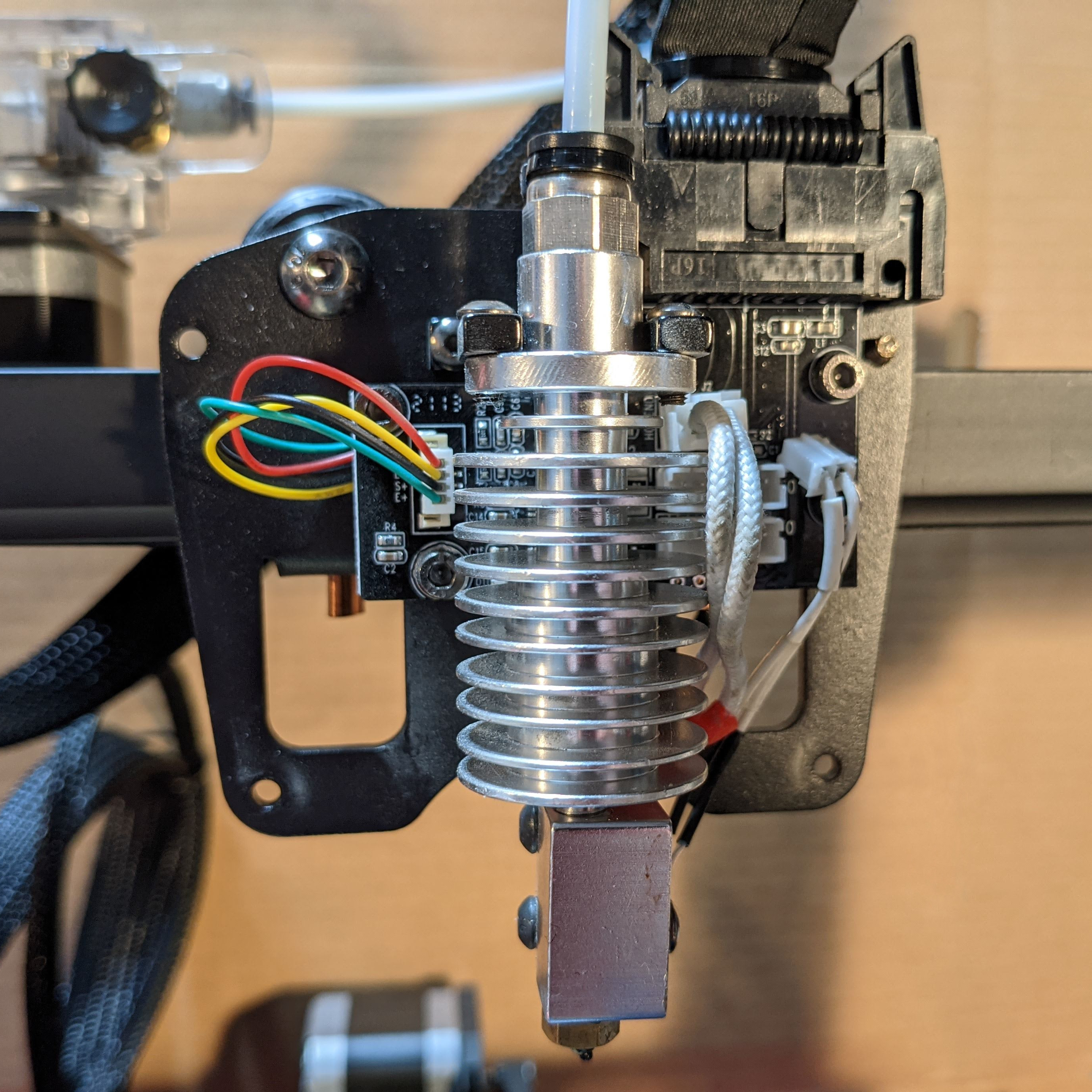
The Anycubic Vyper’s extruder assembly contains a fork-shaped metal mount for the hot end which has a strain gauge built into it. This turns it into a load cell similar to what would be found in an electronic scale.
Any force exerted on the hot end will slightly deform the mount, and the strain gauge turns this deformation into an electrical signal that can be measured and quantified. Even very light pressure on the hot end can be detected in this way.
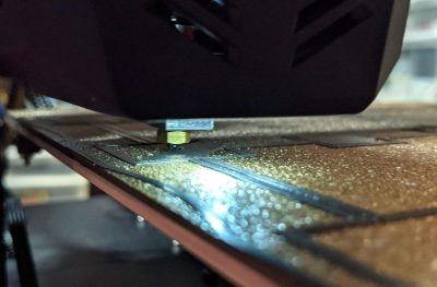
Thanks to this functionality, the nozzle itself becomes a touch sensor. When the machine is directed to auto-level itself, the extruder is repeatedly lowered toward the build platform until the nozzle comes into contact with it. Even a light touch can be reliably detected, so this process doesn’t involve much force.
By taking multiple measurements in a grid pattern, mesh leveling can be implemented. Also, since the physical distance between nozzle tip and build surface can be sensed, a reasonable Z-axis offset can be implemented automatically, leaving the operator to worry only about fine tuning.


It’s a neat idea, and the extruder has clearly been designed around the feature.
Results? Perfectly Serviceable
How well does it work? I’m happy to say the feature appears to work as advertised, including the automatic setting of an effective initial Z-offset.
One simply installs the build plate, makes sure the nozzle and the build surface are clean, then instructs the printer to perform the auto-leveling process. The machine will pre-heat, ensuring calibration is done under printing conditions instead of cold, and then the nozzle touches the build platform in a 4 x 4 grid pattern, after which it silently applies mesh leveling and an initial Z-offset that can be fine-tuned if desired. In theory, the process doesn’t need to be repeated unless the build platform changes, but the user can trigger the process whenever they wish.
There Are Limits
The auto-leveling works as advertised, but there are limits to what it can do. First of all, problems related to the quality or type of filament, or the material of the build platform, are separate issues that can still trip up a novice. These are not fixed by an auto-leveling feature.
Both the print surface and the nozzle tip must be clean in order to get the best results, so it’s best to unload filament from the hot end before auto-leveling. Because the machine pre-heats and touches each grid point twice, a loaded nozzle leaves little dabs of molten plastic at each point, and this extra material between the nozzle and the build surface can affect the accuracy of measurements. Indeed, this might be the Achilles heel of all nozzle-based sensors.
There is a limit as to what can be sensed and modeled with a 4 x 4 grid of touch points. A build surface with serious imperfections might not get modeled accurately. I briefly tested this by using shims to simulate mixed high and low spots of up to 0.8 mm in the build sheet before running the auto-leveling process. Unsurprisingly, a 4 x 4 grid of touch points was insufficient to accurately model where exactly these imperfections started and stopped, but I was pleased to see that the resulting first layer was at least still serviceable, if a bit thin and overly-squished around some of the high areas. It would be nice to have an option to increase the number of measurement points, or perhaps manually refine the mesh, as a way to better deal with special cases.
Lastly, the machine’s firmware is not very verbose about the details of its auto-leveling process. There seems to be no way to modify the sensitivity, no way to see the actual measurements taken, and no way to manually fine-tune anything other than the Z-offset, which can be changed up or down in 0.05 mm increments.
Is This The Way?
The Vyper’s auto-leveling and initial Z-offset work as advertised and give serviceable results, even if the firmware is a bit quiet about what exactly is going on under the hood. It’s awfully convenient, the strain gauge integration looks solid, and as a whole it’s a clever system that’s nice to see in a factory offering.
What do you think about this method of automating away the dull drudgery of bed leveling and first-layer tuning? Is turning the hot end into a load cell the right way to go? We want to know what you think, so let us know in the comments.


The Fisher delta printer has always had bed leveling, one click of the GUI and it does it. I’ve not used anything else on this printer.
Even earlier, printerbot had perfect autoleveling almost ten years ago with an inductive probe. A perfect flawless level every time with firmware and a 25 dollar part. How has everyone not learned this by now?
As stated in the article, inductive sensors still require the user to determine and manually set the Z-Offset of the extruder. By making the extruder the sensor, the offset can be automatically determined.
It also means that you’re flexing the entire extruder assembly several times before each print. I’d love to see some published repeatability numbers on this approach as you’re intentionally removing rigidity in order to accomplish this measurement.
Prusa’s approach is high precision and which leaves the accuracy to the user.
Its flexing the extruder basically nothing – well within the limits of the material it will stick in a pretty consistent location, more than good enough for FDM.. Also shouldn’t really loose rigidity enough to matter in any direction – like any flexure mechanism its not quite as good as pure solid, but only really moves in the intended direction…
Not a feasible approach for high load applications where that compliance will be too much to maintain precision like milling but 3d printing won’t be harmed, the act of extruding is basically zero force on the print head, and even at pretty high print speeds the x-y precision shouldn’t be changed meaningfully.
Though if you use this method at the really, really fast, build a printer designed to print at meter a second or better, damn the cost levels of fast it might come in to play as you really are throwing that extruder’s mass around really really rapidly then, and its got to be a pretty heavy extruder to melt plastic that fast too. But at normal print speeds the mass of the extruder with those printer acceleration shouldn’t deform the spring in normal use enough to matter.
That is, if the firmware supports it. the CR6-SE, for reasons unknown to me, either didn’t do the offset at all, and the mesh leveling only kinda worked. I’ve not played with the community firmware enough to report back on if it does a good job, but I do know that it does not automatically set the Z offset.
The printrbot in question was the Simple Metal and others in that generation of products, and it worked rather well despite only having three reference points to use in it’s firmware.
This is basically meaningless in practice. You only ever have to change it if you replace the print head.
At that point you’ve already dismantled the printer, so what’s adjusting one number?
This article is somewhat timely for me, because I am currently locked in mortal combat with the bed leveling built into a cheap 3D printer. It’s one of those capacitive sense probes, and I swear it’s haunted. I run the Z-probe offset calibration, and everything is just fine. I run a print, and it’s printing a half-millimeter in the air. I run the calibration routine again, and I get the exact same offset as the first time!
I think there might be a software component to the problem, because it runs a 3-point bed levelling routine at the beginning of every print, which perhaps gives different results than the calibration.
At this point, I think I might swap out for one of those BL-Touch things that the article mentions. I imagine that a physical switch gives more repeatable results than a possibly-sketchy capacitive sensor, and I like the idea of being able to mechanically set the probe height, without having to bother with an offset.
Capacitive sensors, by nature, are incredibly unreliable. Any change in temperature or humidity can throw the sensor off (just breathing on it can change the values). They’re good enough for a rough pass to level by hand, but they’re really awful for any sort of repeatability.
Look into Gcode M851, which defines the probe-to-nozzle offset. When that’s adjusted properly (manually in your case, and in mine), this issue goes away.
I had a printrbot simple medal with the inductive sensor. When I added a heated bed it completely threw off the sensor. I found I had to heat the bed, turn it off, then do the levelling.
Old news? I have a Creality CR6-SE here that uses a strain gauge for leveling. It’s been around for quite some time now.
… and no, its still not hassle-free.
It puts pressure on the bed, and the bed has a little give which varies over its surface. So the printer “thinks” the bed is uneven in areas that are actually flat.
I’ll still take it over manual leveling though.
I had that issue with a bed on springs when trying to use a piezo sensor for bed leveling. It was too much hassle, so I went back to using a BLTouch.
I solved the same issue by removing the springs and replacing them with solid spacers. Also replaced the bed screw nuts with nylock versions and nothing has moved out of alignment since.
You probably need to adjust the strain gauge pot – if it’s set too “heavy” then this is an issue. Get it right and you barely have to touch the nozzle to trigger it.
You need to adjust the sensitivity of the sensor, there is a little pot on the head board you can adjust
I always wondered why this wasn’t a normal way to handle Z height setting. Since the nozzles aren’t frequently swapped.. Good to see it implemented.
I wonder if it would be possible to level the bed by observing the power draw of the Z stepper. Move the bed upwards until it contacts the nozzle. When the bed meets that resistance, the Z stepper should spike, right? If that spike comes in fast enough, then the printer can use that as the Z height for that location.
This would improve upon the nozzle-strain-gauge method by removing complexity from the hotend, which is already the most complex, delicate, and frequently replaced part of the printer.
Sensorless homing is supported in Marlin with certain stepper driver: https://wiki.layerfused.com/en/general/marlin-firmware/sensorless-homing
However it is not recommended/supported for z homing with lead screws. A Z axis with lead screws can have a very large torque multiplier and when you ram you nozzle into the heat bed, the motors may not see much resisting force.
I’m guessing that before the stepper impedance would change sufficiently to be meaningful, the bed would already be under enough force to deform it.
It might work with a belt-driven Z-axis, but not with a screw-driven one. Lead screws are specifically meant to resist backlash and backdriving, so the drivers won’t see the stall until it’s putting a considerable force behind the tiny nozzle tip, and may in fact happily drive it straight through the print bed.
i don’t want to add anything else to my end effector (maybe i’m just too lazy or uncreative), so i still do mesh leveling manually…have a perl script that runs on the PC sending G-code to move the head around the bed, and i have it descend in 0.05mm increments until the nozzle pinches a piece of paper that i use as a feeler gauge. i’m a walking talking example of the “before” problem in this article and i’m bummed that i need to repeat it about every six months.
https://hackaday.com/2019/01/27/quartet-of-smd-resistors-used-to-sense-z-axis-height/
Been there, seen that
Linked in the article.
I had a Cube 3D and I have a Stratasys. The Cube 3D used an LED/emitter combination to reflect light off the build plate in 9 locations. You’d run the leveling routine and it would tell you to turn one or two leveling screws to lift corners of the plate. I wasn’t quite sure how it was supposed to work and it was kind of hit or miss. You’d run the routine, adjust the screws as it told you to, and then it would run again, fail and tell you to basically undo what it had previously told you what to do.
The Stratasys gets around all this by being a chonky huge machine that has a rigid bed surface that the build trays slide onto. The bed surface pulls the plastic trays flat and the Z-probe measures the plate surface in 4 locations. It’s just one of the ways that these machines are a bit more user-friendly. If you have room for a 300 lb, refrigerator-sized machine, I definitely recommend it.
I would guess that with a bit of software-smartness, this nozzle leveling could be improved. Should not be too hard to do a nozzle cleaning by probing the bed on one of the sides to the bed to get a rough idea, do some retract to the extruder and wipe the nozzle on the bed there, before you actually move over to the real probing grid and get the bed level measurements done. If you are worried about oozing, you could probably do a little wipe motion around the probing point, just before you actually go up and touch down to measure on a clean spot… at least that would give more repeatability if you’re worried about random ‘buggers’ stuck to the nozzle.
This area of 3d printing has always confused me as its one of the most important steps to getting good prints. Once you learn to level on the fly with the skirt of a print, you’ll never have leveling issues again. What do people do to their printers that they need to re-level every print? I only need to relevel after a particularly stuck print or once every 5- 6 prints. Even then, its a fine tune adjustment…
Teaching people to use a piece of paper and feel the drag is IMO equivalent of using an axe for woodworking. Yes its done but its done as the ROUGH stage. Still need to fine-tune afterwards. Adjust each corner as is needed while the print is doing its skirt thing and you’ll be good to go.
Don’t trust auto-levelers…
All the auto bed levers I’ve used were reliable. I could trust them enough to start a print remotely. I think manual bed leveling is a nuisance. I agree the first layer is very important – that’s why I installed bed leveling :P
“I think manual bed leveling is a nuisance.”
^
This. I retired my oldest printer for this reason as the main board is very old proprietary 8 bit and doesn’t allow for expansion. All my other printers have autoleveling which I have setup in my slicer to do before every print. No fails that way and I can use my time to actually print and not waste it in a cumbersome manual procedure.
“Once you learn to level on the fly with the skirt of a print,”
This!
I started with the “grab a piece of paper” method because it’s what everyone says to do. But that was always a pain in the ass and doesn’t even give the best results. Instead I “designed” a 1-layer tall circle that is just a little smaller than my bed. If my bed has been thrown totally out of wack then I start by just eyeballing it until I can move the nozzle all around the bed at 0-height without crashing nor floating in the air. Then I print my test print. I can see which bed screws need tightened or loosened by looking at the bead as it is layed across each quadrant of the bed. Sometimes I even adjust the screws as the test print prints, other times I feel less lucky so I pause it.
I assume your method is similar only you are using the skirt of the actual item you want to print. I’ve thought about doing it that way too but I want to get it trammed across the area of the bed as far as possible, not just the part I am about to print in as the next part I print might be elsewhere on the bed and I don’t re-tram between every print.
Someone get its. I get it close and then adjust the screws on the fly like yourself. And I never have to get on Reddir to tell the world my BLTouch isn’t working.
I had a very simple concept for this – move the Z limit switch onto the extruder carriage, triggered by the extruder being lifted. In this design, the extruder would be mounted on a pair of vertically oriented pins, with enough travel to allow triggering of a microswitch.
Then, any impact with the bed would lift the extruder on the pins, triggering the Z-switch, and the profile of the bed could be mapped.
That takes a lot of travel between the two trip points of the switch, which means play in the nozzle. The strain gauge solution triggers on micrometers of strain.
If I understand your idea correctly, this is similar to what the Robo R1 does.
I have used such a printer for the last 5 years. The print head moves along one major horizontal smooth rod to support it. It is held vertical by a second horizontal rod that it is spring loaded against. The print head has electrical contact with the second rod and when the printhead pushes on the build board the print head swivels on the bigger horizontal rod and breaks the circuit. This becomes a very simple and reliable nozzle pressure sensor. I use it with Marlin bed levelling, and I find it quite serviceable. What is there to go wrong?
Well quite a few things. The most difficult to allow for is the inevitable springy-ness of the bed. How stiff should the spring loading be? Too hard and the system is not sensitive enough and bends the board reporting distortion that is not really there? Ok, lighten off the spring. But make the spring too weak and the head is not held rigid enough. The trade off point for sensitivity versus rigidity is hard to find as the flexing of the bed supports can vary across the board.
Using a sensitive load cell that also is relatively rigid sounds good to me. It should be possible for such a cell to be able to determine what sort of rigidity the build board has by analysing the change of force versus distance as the nozzle presses, harder and harder into the build board..
I have spent some time thinking about this and wondered about this idea. How about if the load cell was sensitive enough to first detect the build board, but then also sensitive enough to be able to detect spurts of plastic being squeezed against the the build board. Some maths could determine the gap to cause the ideal “lifting pressure/force” caused by the extruded plastic, and then to judge how much plastic to lay down. This would also automate the z-offset and could have different profiles for different plastics. The load cell in a set of kitchen scales would go close to the combination of rigidity and sensitivity required I reckon.
But then there is always painter’s masking tape. Which is my fall back solution. At least my system automatically compensates if use tape on the bed. If you look up my Robox rebuild article on this Hackaday site you see more of where I am coming from
Rob.
Part of the problem is: Most 3D printers are made too flimsily to have one of their prints removed without going out of adjustment. If a printer is strong it will only have to be adjusted once in a very great while.
If you think that you are going to move a Bridgport’s knee .1mm with gentle pressure, you make be wrong.
“Both the print surface and the nozzle tip must be clean in order to get the best results, so it’s best to unload filament from the hot end before auto-leveling.”
Suction clearing the nozzle?
Printers used to have (and most still do) poorly designed and built beds and leveling systems. You used to have to manually adjust the level before every print and it didn’t work well because of the crappy beds and even crappier leveling systems. But that’s been fixed, sort of. Instead fixing the actual problems, people just automated the leveling process they used to do manually – threw more hardware and software at it. Now, the machine does it- when it works. And when it doesn’t you can’t print at all. They’ve traded a simple problem for a very complex one. Is that really an improvement?
I decided to fix the actual problems instead and designed bed and support system that doesn’t require releveling unless I take apart the Z axis. Nope, no autoleveling, no mesh compensation, no extra motors, no extra drivers, no extra cables, no complex configuration, no bed sensors. Just simple physics- a flat, thermally conductive bed plate, and a kinematic mount with two leveling adjustments. I have transported my printer laying on its back in my car or in the back of a truck, taken it out and stood it up and started printing without any adjustments on many occasions. It just works.
A few others have built similar designs, but you probably won’t see them on youtube because they don’t have a bunch of whirring motors and spinning screws and tilting beds to show off. And no bearded dopes making silly faces on the thumbnails because for some reason that increases the click-through rate. Printers that just work are boring to watch… but great to use.
Do you have a link to your design (or similar one) on YouTube? Thanks.
No youtube videos- that would be boring, but I have written some blog posts:
start here:
https://drmrehorst.blogspot.com/2017/07/ultra-megamax-dominator-3d-printer-bed.html
https://drmrehorst.blogspot.com/2017/08/thermal-performance-of-ummds-print-bed.html
https://drmrehorst.blogspot.com/2019/04/more-changes-to-ummds-z-axis.html
Thank you for sharing. I don’t like videos either, so a good write-up is a welcome change.
Oh and if you post a lot of links, I think the post gets manually vetted, and (eventually, usually) makes it into the comments. It’s a pretty clunky system.
I can’t seem to post links here, but do a search for “blogspot mrehorst” or “UMMD 3D printer” and search through the posts. There are a few that are relevant to the bed design/construction:
The first was made on 7/17, another on 8/17, and another on 4/19.
https://hackaday.io/project/28933-kinematic-mount-for-3d-printer-bed
“Printers that just work are boring to watch… but great to use.”
Rockets that fail to work are interesting to watch.
I wonder how many people could solve all their problems with a simple feeler gauge. Lots of software people in the ‘community’ wasting their own time – very few wrench turners.
PyrO-Piezo has been doing this for a while now and it also allows you to retrofit it to any printer.
It uses a piezo sensor, not a strain gauge, but it works lovely.
There’s a couple of design mistakes which are repeated far too often, and are the cause of the entire bed-levelling subindustry.
The first is that anybody who has set up a traditional laboratory balance or a traditional optical microscope would probably have noticed that it had three- not four- levelling screws: it is extremely difficult to level a comparatively-thin plate with four screws without introducing a warp.
The second is that any printer design which has two Z-axis stepper motors but a limit switch or endstop on only one of them is asking for trouble: every power interruption and every filament-load operation will almost certainly jog one more than the other. Now, about that idea of unloading the filament in order to level the bed…
Unfortunately, 3 screw leveling systems exist. And in practice, the corners on the side with the single screw always droop.
And that means the plate is not thick enough. Pretty easy to solve.
4 point is not hard, if you’re methodical: Put a straight edge across diagonal mounting points. Adjust until there’s no light coming through under the ends or middle. It is now flat (unless your plate is lumpy. If it is, fix.) From here you can keep it flat during any of these moves: 1) adjust two adjacent corners the same amount, 2) opposite corners an opposite amount 3) if your bed mounts form a square, adjust one corner, and its two neighbors half as far. Sound confusing? Not really: to tram your flat bed, move the nozzle over a mounting point, and adjust that and the next clockwise point the same amount to zero out the point. Move to the next clockwise point and repeat. Move clockwise again and repeat with the third point. Done. (You can verify by repeating the process, in case your “same amount” varies.)
That’s a great method.
Mic-6 and 3-point kinematic mount, and bed leveling is something you only do to begin with (but you still need multiple mesh profiles for different temperatures, of course).
My company’s Hydra Research Nautilus is pretty trouble free with bed leveling. Can’t complain really. For that matter, my Lulzbot Taz from several years ago mostly worked (only having problems when gunk got on the nozzle and interfered with conductivity-based probing.)
I have the CR6SE. Stock firmware on it was serviceable but not great. There’s a fantastic community around most Creality printers and as a result some of those folks have come up with custom firmware (currently v6.1) which improves on the original firmware in so many ways…
– Built in mesh visualisation (and ability to manually adjust individual mesh measurements)
– Built in mesh test print
– 0.01 z-offset adjustment
– On the fly retraction adjustment
That’s just a few of them.
“Use the babystep option to adjust your first layer height!” – was the best advice I got starting out.
Sorry to go a little off topic but I’m very happy to see you referred to leveling and “first layer calibration” individually!! Most tutorials lump the two together and trying to set both using the screws was a horrible experience.
Now that I leave the height tuning to a separate step I see auto bed leveling as a nice-to-have but not really needed. If I moved off of glass I might reconsider.
note: the babystep feature is only on newer Marlin firmware and then is only available once the print starts. It’s in the Tune menu and looks like it’s now called Babystep Z ( or Z Probe Offset ).
Most people automatically blame the bed as the culprit. However, the XY motion mechanism can also have twist and dish.
One mechanism that I’d love to see explored is having an electrically conductive bed with a circuit that can detect electrical continuity between the metal nozzle and the bed.
like on a mill? I think that’s been done (can’t find a source at the moment but I know I’ve read about it before) but I think it suffers from a few issues, like oozing on the nozzle here too, the filament oozing over time or spreading out on the nozzle as it prints causes a tiny layer to build up preventing conductivity as it touches against the bed and the head just keeps smushing into it. I’d like to see a an additional switch involved as a failsafe if I was to take that approach (manually set about .5mm below the first calibration) and if it was triggered maybe stop the print or do another wipe and try again. There are some filaments that do better printed on glass so a pressure triggered one (rather than an optical/inductance/capacitive/conducting sensor) might be the best of all the options
Hi Donald et al, I’m wondering why tramming is done at fixed points i.e. at the intersections of the horizontal and vertical grid lines? Would it not be better to travel those grid lines? My thinking is that you would collect many more points and still determine know the intersection points plus the intermediate ones too. I guess in this case it would work best with an induction type sensor.
Lots of people in the comments either suspicious or damning of any kind of automatic bed levelling. You’re all crackers … why wouldn’t you want automatic bed levelling that just works? I sometimes feel the 3D printer community has a lot of gatekeeper vibes. Eventually when there’s a 3D printer that requires pretty much zero effort with anything everyone will hate it because it’s no longer a tinkering hobby and you no longer need to be “clever” to 3D print.
I have a CR6SE with the community firmware and the bed levelling works brilliantly.
The strain gauge only caused me issues when installing an extruder for direct drive – but this was easily fixed – the hot end and Bowden need to be free to move – and I had inadvertently added some friction due to the design of the mount. The causes the strain gauge to report much lighter values by mistake.
I never bother removing the filament when levelling and don’t appear to have any issues. The filament is hot and I think just gets melted out the way when the nozzle hits the bed. I level the bed every now and then – it’s so quick I don’t really ever worry about it.
The prints are constantly great – and I never have to think about levelling.
I’ve been really happy without for eons it feels like – if the machine is repeatable, copes with the minor differences in thermal expansion of materials and sturdy enough you don’t need to level the bed again, do it once get great results all the time.
All the automatic levellers do have downsides, so there are reasons to wish to avoid them – I do like the concept though, and expect to be building it into the next printer I build as it is useful enough IMO. Also lets you get away with less than optimal machine design for whatever other constraints you have and get better results.
It’s more the multi point mesh levelling stuff that’s great – any build surface is going to have variations. So it’s not so much levelling but flatness.
Hard spring under the bed + marlin auto bed leveling 9 points. This is the way.
I wonder if it does a wipe before it does the print would it help in repeatability (or at least unattended calibration). I’ve an anycubic mega i3 and it oozes a bit after a print (retraction be damned – probably the nature of not having a direct drive). heating the nozzle and doing a wipe on some heat resistant material (https://hackaday.com/2019/11/20/fail-of-the-week-the-3d-printer-nozzle-wipe-that-wont/) beforehand might improve accuracy. I know with my printer the ultrabase bed expands even more after its been on for a while so consecutive prints without a full cooldown are a problem.
I have a Prusa MK3. I believe most of our problems are due to leveling prior to each print after preheating the bed and the nozzle causing filament to ooze out of the nozzle and affect the leveling process. Haven’t “fixed” it yet. Don’t know how unloading filament prior to each print so that you may level the bed is going to work. Do you preheat, unload filament, level bed, load filament, then print each time? That would add at least 15 minutes to each print. Even a 20 minute print.
Resetting the Z axis every 3 or 4 prints works most of the time for me. Another issue is “missed” Z steps causing the 2 z axis to go out of sync with each other affecting the “leveling” of the bed.
Fixing the filament spool / feeding mechanism is another source of missed steps that affects the “leveling” of the bed. I have my roll on top of an enclosure running on rods supported with ball bearings. A weight screwed into the spool adds heft and a rag under the spool slows it down and keeps the filament tighter limiting the amount of unwinding that may occur. We also need to limit quick lifting of the head as that feeds filament backwards and may cause it to unwind, then bind. We check this during each Z axis calibration and after lifting the head after each print.
Lastly I’m using an after market metal build plate, as I got tired of waiting for an official coated metal plate from Prusa. The coating on my plate is wearing out and its probably time to either flip it over or buy a replacement. When it was new it worked flawlessly but lately (15 spools later) it isn’t working as well.
Any analog measurement is going to have 50 to 100 mV of noise on it. I don’t know if Prusa performs averaging of the readings from the Minda Probe. Putting the A/D convertor as close to the device as possible and transmitting the digital reading to the control board would reduce the noise. A Minda Probe with an A/D converter and I2C bus built in would be my first choice to improve the reading along with taking 8 to 16 samples per reading depending upon the standard deviation of the average.
Good analog measurements require well regulated power and ground. If the voltage drops or ground level shifts when the heater is being regulated and you are trying to measure the position of the bed then that could be a problem. Haven’t looked at the A/D circuit being used and its sensitivity to voltage etc.
Given all these potential issues I’m really happy with my MK3.
Also we would still have the issue of setting the Z Offset. I’ve had to reset it a few times as it has moved over the course of six months. No idea why the Z Offset might need to move on an MK3 with a Minda Probe.
You can use bobstro’s start g-code to avoid the oozing. It preheats the nozzle to 160C before the bed probing, then heats to final temperature afterwards. It’s a good fix.
https://projects.ttlexceeded.com/3dprinting_prusaslicer_start_gcode_mk3.html
Printering? Printerizing!
Pressing the heated nozzle into a removable magnetic surface will damage the surface at every probe point.
I have a large custom-made delta with two hot-ends. Calibrating deltas is a lot harder than regular designs and even harder when you want both size and precision. My printer evolved through about 5 versions over the last 6 years and here is my experience. (BTW, I ended up with the method of this article. It’s not perfect and the concept has actually been around and used for some time.)
-FSR (force-sense-resistors, three under the bed): sensitive to pre-loading (because the bed has to sit/clamp down on them) and location of the probe point. Also affected by changing the temperature of a bed. Failure can lead to crashing the nozzle. Also slower because the bed must be approached slowly.
-Reflective IR sensor: lateral offset from probe can be a problem (smaller print region, errors from tilted hotend, especially for a delta. Also sensitive to bed surface, especially glass. However, non-contact methods can be fast because they allow overshoot without crashing the nozzle.
-Hotend-on-a-switch: Good concept, bad idea. Anything that allows play in the nozzle is asking for trouble.
-Mechanical touch-switch (early classic approach): fast and reliable and works on all surfaces. However, needs to be moved in and out of place. Also, the lateral offset mounting has same problems as above , especially on deltas (early calibration mapping, ugh!)
-Piezo sandwiched between hot-end and it’s mount: accurate, not sensitive to pre-loading, works on all surfaces. However, as a contact method it can’t be really fast. Also, a piezo only generates a signal when the pressure is CHANGING. You can push down slowly and not get a trigger. Watching a slow-motion nozzle crash is painful. Also, sudden travel moves can cause spurious signals because lateral forces on the hot-end can translate into vertical forces. However, with proper tuning of the probing speeds/accelerations and the sensitivity of the piezo signal, it can work pretty fast. My bed is large and a mesh pattern is like 10×10, so I don’t do one every print. My repeatbility is good enough that I only tap once and don’t worry about liquid ooze on the tip. One retraction beforehand doesn’t hurt though.
Advice: Get your mechanicals as accurate as possible. My bed has no level adjustment, just sits on the triangular base. It is 375mm across, 1/4″ thick MIC-6 aluminum. Glass is a great print surface but I broke several from nozzle crashes, is a really poor temp conductor, and can be a problem for some sensors like IR. You also can’t machine it for screws or anything!
After a 7-point bed-leveling probe I get .03mm RMS across a 12″ wide zone. More valuable knowledge is the .2mm pk-to-pk un-flatness. I use a 10×10 mesh-bed compensation to get rid of that and I can routinely print wide .1mm first layers. I don’t bother re-leveling the bed or doing mesh-compensation unless I’ve messed with the frame/bed or changed nozzles/hotends. Just one probe in the center to find the exact zero height before my first print of the day (although I do it more often to feel safe).
I wanted a kobra and ordered one directly from anycubic. At the checkout page, I added 1kg of PLA so I would have some to start printing a few projects that I needed done. Ordered May 10 and on May 14 I received…. PLA. No printer. My card was charged $329.00 but all I got is PLA. I have emailed anycubic several times. No reply. I cannot get to a page to return the PLA and I cannot get anyone to respond to ANY request. I am now contacting my credit card company and a lawyer.
DON’T BY ANYCUBIC!
I expect that strain-based autoleveling is a planned-obsolescence scam.
Do you REALLY want your brass nozzle pressing against your PIE bed n times before each print?
Not I.
This actually is a reason NOT to get the 3V3 Plus I was thinking about.