We all know that light and sound are wave phenomena, but of very different kinds. Light is electromechanical in nature, while sound is mechanical. Light can travel through a vacuum, while sound needs some sort of medium to transmit it. So it would seem that it might be difficult to use sound to modify light, but with the right equipment, it’s actually pretty easy.
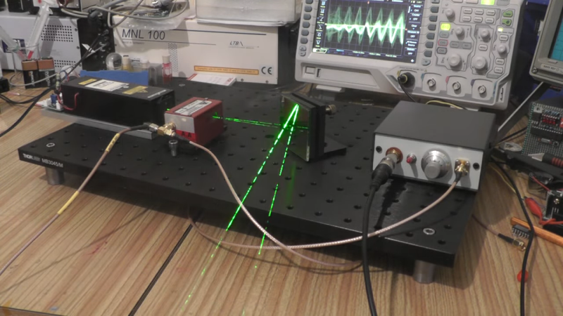
Easy, perhaps, if you’re used to slinging lasers around and terms like “acousto-optic tunable filter” fall trippingly from your tongue, as is the case for [Les Wright]. An AOTF is a device that takes a radio frequency input and applies it to a piezoelectric transducer that’s bonded to a crystal of tellurium oxide. The RF signal excites the transducer, which vibrates the TeO2 crystal and sets up a standing wave within it. The alternating bands of compressed and expanded material within the crystal act like a diffraction grating. Change the excitation frequency, and the filter’s frequency changes too.
To explore the way sound can bend light, [Les] picked up a commercial AOTF from the surplus market. Sadly, it didn’t come with the RF driver, but no matter — a few quick eBay purchases put the needed RF generator and power amplifier on his bench. The modules went into an enclosure to make the driver more of an instrument and less of a one-off, with a nice multi-turn pot and vernier knob for precise filter adjustment. It’s really kind of cool to watch the output beam change colors at the twist of a knob, and cooler still to realize how it all works.
We’ve been seeing a lot of [Les]’ optics projects lately, from homemade TEA lasers to blasting the Bayer filter off a digital camera, each as impressive as the last!


Scophony did some remarkable work on a liquid version of this using the Jefree Cell for projection television.
Yes and that was in the 1930’s, I tried to build a Jefree cell without success, could not cut a 10 thou thick crystal good enough to oscillate at 10 mhz, some good advise for making the driver in the video.
vibrates the TeO2 crystal and sets up a standing wave within it is exactly opposite to what is needed.
A standing wave would only permit a relatively small number of fixed resonant frequencies, but you want to freedom to choose any frequency within its tunable range. Les mentions it but mispoke it in the voiceover, while showing a diagram plainly showing an absorber that is there exactly to suppress resonances.
Les didn’t mention it, but these things are cool because the propagating acoustic wave also Doppler-shifts the light: the light output frequency is shifted by the ~100 MHz excitation frequency: The modulator can modulate the light in AM, FM and phase. It can also do it on several wavelengths simultaneously. Kinda neat.
“Light is electromechanical in nature, while sound is mechanical.” I think you mean that light is /electromagnetic/ in nature.
More than 20 years ago, when semicinductor lasers was weak and uneffective, that devices named AOM (acousto-optic modulator) and frequently used to modulate laser beam from gas tube lasers. Frequently used to do laser shows. Also there was PCAOM (polychromatic acousto-optic modulator) that worked with multicolor gas tube lasers (white lasers) and allowed to control the color of the beam, modulating every spectrum line separately. They usually had 4-8 channels. Most of AOMs and PCAOMs was manufactured by NEOS. I think it is possible to find that devices along with drivers for cheap, search for NEOS PCAOM.
Now that kind of devices is out of fashion, since we have easily controlled and powerful semiconductor lasers.
Our NEOS accousto-optical devices steered a 200mW green laser diode. This was ca. 1990, at Naval Ocean Systems Center. Later versions used a 1 watt Krypton/Argon gas laser.
“This was ca. 1990, at Naval Ocean Systems Center.”
Leading up to experiments in mounting lasers on sharks!
B^)
Naah. The sharks were too unpredictable. Dolphins, however, could be trained to retrieve things.
I used to have a film recorder that used an AOM to modulate laser beams onto 35mm film. It was almost as big as a minivan but it worked great!
Get yourself two of these, and arrange them one after the other, with the first steering left/right and the second oriented to steer the beam up/down. Now you have a beam that can be directed anywhere on a plane. Now point that at a volume with a spinning helix painted white, spinning at 60 rpm, with a hall device detecting a magnet on it’s perimeter to synchronize the spinning surfaces with the code driving the DACs that modulate the RF that’s steering the beam, and you have a 3D display device that supports group viewing of 3D objects rendered into the space.
Unforunately, AOMs have a small steer angle. You had to use lenses assembly to make it wide enough to be useful. However, lenses gave beam power loss and divergence, so you got a dim image. So, most used galvos for steering and AOM to modulate the beam.
Spinning helix volumetric displays certainly was simple and funny devices, but hardly really useable.
They sometimes felt dangerous to be near – 5kg of sharpened Al sinning at 600rpm? I left the project before they ‘graduated’ from 13″ dia. to 36″ dia. What could go wrong.
The code ran on a 386sx with 2M or RAM. I wrote it in Zortech C++, developed and used my own text-based window/menu system for the UI.
The problem with galvos, as opposed to the crystals, is lack of random access. You need random access to do a reasonable job of rendering into the space.
We had a 4096-location buffer (24 bits (12 bits for x + 12 bits for y) * 4k). At 600 rpm the two blades rotate through 180 degrees in 1/20th of a second, giving you a 20 Hz refresh rate and 4096 angles into which you can place one dot. Your next dot may be quite distant from the current dot (we drew point clouds and vector lists).
I added the ability to render sprites in the volume by the expediency of stealing ‘slots’ from other areas of the display while the small sprite was rendered moving around in the volume. We had a demo of a pointilist ocean surface, a simple wireframe of an aircraft carrier on the surface. Two sprites – a submarine and an airplane – moved around on ple-plotted courses over a 30-second live rendering cycle.
The limitation of these devices is the time it takes to settle to a new vibration while the old vibration fades away. The BeO2 crystals I used required about 13uS to settle, limiting voxel count to about 4000. Hopefully your TeO2 crystals settle faster.
you can put the AOM inside the laser cavity to make a Q-switch laser and if you take care can even mode lock the laser
Cheers
Steve
An AOM’s switching time of ca. 10 us is awfully slow for a Q switch. Might work for some gain media, though with a lot of resulting jitter. Likewise modelocking, where generally the switch is in the sub-ns range — you need the switch transition to be faster than the cavity transit time (a few ns at most).
There are acousto-optic q-switches, but the way they are configured is that with no signal they are in the ‘on’ state and with a signal they are ‘off’, effectively the reverse behaviour of an AOTF.
I have watched the signal on an Oscilloscope on an AO Q-switch running at 80MHz. It seems they optically switch abruptly once the vibrations in the lattice have ceased, though I would have to check the literature on that one. (Or someone feel free to correct me)
The AOTF would be unsuitable, mostly because of its low damage threshold.