An acousto-optic tunable filter and laser

Acousto-Optic Filter Uses Sound To Bend Light

We all know that light and sound are wave phenomena, but of very different kinds. Light is electromechanical in nature, while sound is mechanical. Light can travel through a vacuum, while sound needs some sort of medium to transmit it. So it would seem that it might be difficult to use sound to modify light, but with the right equipment, it’s actually pretty easy.

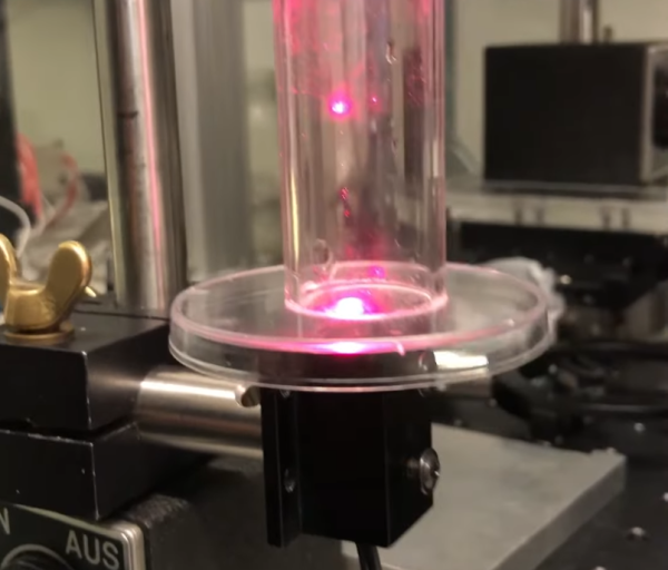
Easy, perhaps, if you’re used to slinging lasers around and terms like “acousto-optic tunable filter” fall trippingly from your tongue, as is the case for [Les Wright]. An AOTF is a device that takes a radio frequency input and applies it to a piezoelectric transducer that’s bonded to a crystal of tellurium oxide. The RF signal excites the transducer, which vibrates the TeO2 crystal and sets up a standing wave within it. The alternating bands of compressed and expanded material within the crystal act like a diffraction grating. Change the excitation frequency, and the filter’s frequency changes too.

To explore the way sound can bend light, [Les] picked up a commercial AOTF from the surplus market. Sadly, it didn’t come with the RF driver, but no matter — a few quick eBay purchases put the needed RF generator and power amplifier on his bench. The modules went into an enclosure to make the driver more of an instrument and less of a one-off, with a nice multi-turn pot and vernier knob for precise filter adjustment. It’s really kind of cool to watch the output beam change colors at the twist of a knob, and cooler still to realize how it all works.

We’ve been seeing a lot of [Les]’ optics projects lately, from homemade TEA lasers to blasting the Bayer filter off a digital camera, each as impressive as the last! Continue reading “Acousto-Optic Filter Uses Sound To Bend Light”

Pi-Based Spectrometer Puts The Complexity In The Software

Play around with optics long enough and sooner or later you’re probably going to want a spectrometer. Optical instruments are famously expensive, though, at least for high-quality units. But a useful spectrometer, like this DIY Raspberry Pi-based instrument, doesn’t necessarily have to break the bank.

This one comes to us by way of [Les Wright], whose homebrew laser builds we’ve been admiring for a while now. [Les] managed to keep the costs to a minimum here by keeping the optics super simple. The front end of the instrument is just a handheld diffraction-grating spectroscope, of the kind used in physics classrooms to demonstrate the spectral characteristics of different light sources. Turning it from a spectroscope to a spectrometer required a Raspberry Pi and a camera; mounted to a lens and positioned to see the spectrum created by the diffraction grating, the camera sends data to the Pi, where a Python program does the business of converting the spectrum to data. [Les]’s software is simple by complete, giving a graphical representation of the spectral data it sees. The video below shows the build process and what’s involved in calibrating the spectrometer, plus some of the more interesting spectra one can easily explore.

We appreciate the simplicity and the utility of this design, as well as its adaptability. Rather than using machined aluminum, the spectroscope holder and Pi cam bracket could easily be 3D-printer, and we could also see how the software could be adapted to use a PC and webcam.

Continue reading “Pi-Based Spectrometer Puts The Complexity In The Software”

Interference Patterns Harnessed For Optical Logic Gates

The basics of digital logic are pretty easy to master, and figuring out how the ones and zeroes flow through various kinds of gates is often an interesting exercise. Taking things down a level and breaking the component AND, OR, and NOR gates down to their underlying analog circuits adds some complexity, but the flow of electrons is still pretty understandable. Substitute all that for photons, though, and you’ll enter a strange world indeed.

At least that’s our take on [Jeroen Vleggaar]’s latest project, which is making logic gates from purely optical components. As he himself admits in the video below, this isn’t exactly unexplored territory, but his method, which uses constructive and destructive interference, seems not to have been used before. The basic “circuit” consists of a generator, a pair of diffraction patterns etched into a quartz plate, and an evaluator, which is basically a pinhole in another plate positioned to coincide with the common focal point of the generator patterns. An OR gate is formed when the two generators are hit with in-phase monochromatic light. Making the two inputs out of phase by 180° results in an XOR gate, as destructive interference between the two inputs prevents any light from making it out of the evaluator.

Continue reading “Interference Patterns Harnessed For Optical Logic Gates”

A Beginner’s Guide To X-Ray Crystallography

In graduate school, I had a seminar course where one of the sections was about X-ray crystallography. I was excited, because being able to discern the three-dimensional structure of macromolecules just by shining X-rays on them seemed like magic to me. And thanks to a lackluster professor, after the section it remained just as much of a mystery.

If only I’d had [Steve Mould] as a teacher back then. His latest video does an outstanding job explaining X-ray crystallography by scaling up the problem considerably, using the longer wavelength of light and a macroscopic target. He begins with a review of diffraction patterns, those alternating light and dark bands of constructive and destructive interference that result when light shines on two closely spaced slits — the famous “Double-Slit Experiment” that showed light behaves both as a particle and as a wave and provided our first glimpse of quantum mechanics. [Steve] then doubled down on the double-slit, placing another pair of slits in the path of the first. This revealed a grid of spots rather than alternating bands, with the angle between axes dependent on the angle of the slit pairs to each other.


To complete the demonstration, [Steve] then used diffraction to image the helical tungsten filament of an incandescent light bulb. Shining a laser through the helix resulted in a pattern bearing a striking resemblance to what’s probably the most famous X-ray crystallogram ever: [Rosalind Franklin]’s portrait of DNA. It all makes perfect sense, and it’s easy to see how the process works when scaled down both in terms of the target size and the wavelength of light used to probe it.

Hats off to [Steve] for making something that’s ordinarily complex so easily understandable, and for filling in a long-standing gap in my knowledge.

Continue reading “A Beginner’s Guide To X-Ray Crystallography”

Measure Laser Wavelength With A CD And A Tape Measure

Obviously the wavelength of a laser can’t be measured with a scale as large as that of a carpenter’s tape measure. At least not directly and that’s where a Compact Disc comes in. [Styropyro] uses a CD as a diffraction grating which results in an optical pattern large enough to measure.

A diffraction grating splits a beam of light up into multiple beams whose position is determined by both the wavelength of the light and the properties of the grating. Since we don’t know the properties of the grating (the CD) to start, [Styropyro] uses a green laser as reference. This works for a couple of reasons; the green laser’s properties don’t change with heat and it’s wavelength is already known.

It’s all about the triangles. Well, really it’s all about the math and the math is all about the triangles. For those that don’t rock out on special characters [Styropyro] does a great job of not only explaining what each symbol stands for, but applying it (on camera in video below) to the control experiment. Measure the sides of the triangle, then use simple trigonometry to determine the slit distance of the CD. This was the one missing datum that he turns around and uses to measure and determine his unknown laser wavelength.

Continue reading “Measure Laser Wavelength With A CD And A Tape Measure”

RGV Laser

[Carl] sure has come a long way with laser modifications, now introducing his portable RGV Full Colour Laser. Although it feels just like yesterday when he showed us his green spiro and his Lego diffraction grating projector.

But enough of the past, the RGV laser is built using a White Fusion Mixing Kit and his own Full Colour Driver Extension. We couldn’t find any circuit diagrams or code to build your own at the moment, but it appears fairly straight forward and you can always take a look at [c4r0’s] Colour Laser.

Hackaday Links: Sunday January 24

Everyone Remembers Free day right? [The Ideanator’s] Bus Pirate came in such a nice red box – he decided to make it his permanent case.

[Chico] is in the middle of making a CNC, but decided to make some music with the steppers in the mean time.

What looks like an old wooden box is actually [Ludvig’s] super sweet retro arcade cabinet. Complete with a giant emergency stop red button.

Who says Legos are dead? [Carl] used them to create a simple and cheap diffraction grating projector. Including video!

[Torchris] used an Ethernet shield exactly as it was designed, sending data over Ethernet. Still a nice hack for those needing help working with Ethernet shields and Arduino.

Finally [Robert] let us know about a friends Arduino Binary Clock. But we think his elegant use of tape and a sand blaster to engrave glass is cooler.