
Powering external devices directly from a PC’s I/O ports has been a thing long before USB was even a twinkle in an engineer’s eye. Some of us may remember the all too common PS/2 pass-through leads that’d tap into the 275 mA that is available via these ports. When USB was first released, it initially provided a maximum of 500 mA which USB 3.0 increased to 900 mA.
For the longest time, this provided power was meant only to provide a way for peripherals like keyboards, mice and similar trivial devices to be powered rather than require each of these to come with its own power adapter. As the number of computer-connected gadgets increased USB would become the primary way to not only power small devices directly, but to also charge battery-powered devices and ultimately deliver power more generally.
Which brings us to the USB Power Delivery (USB-PD) protocol. Confusingly, USB-PD encompasses a number of different standards, ranging from fixed voltage charging to Programmable Power Supply and Adjustable Voltage Supply. What are the exact differences between these modes, and how does one go about using them?
Bootstrapping communications
To get an idea of how getting power from a USB port works on a hardware level, we will take a look at a chip which implements USB-PD revision 3.0 (R3.0) in the form of the Microchip UPD350. The 3.0 revision of the USB-PD specification supports fixed voltage charging up to 100 W — Standard Power Range (SPR) — with the current R3.1 standard adding Extended Power Range (EPR) which supports up to 240 W. This increase in additional power is accomplished primarily through the use of higher voltages: 48 VDC with R3.1, versus 20 VDC with R3.0.
Despite the prominence of USB-PD, it is possible to draw up to 3.0 A at 5 V without bothering with USB-PD at all, which is a mode that the UPD350 supports as well. This is detailed in Microchip Application Note 1953 (AN1953) as well:
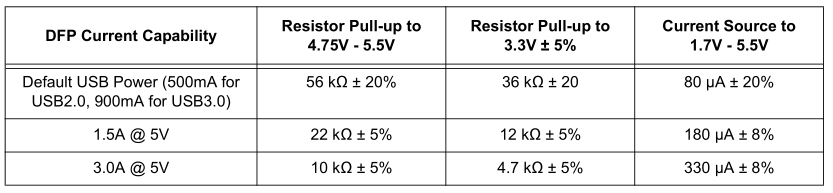
These values pertain to the Rp resistor on the side of the downstream facing port (DFP), also known as the source. By setting this resistor value, the sink (upstream facing port, UFP) can tell the maximum current which the source can provide.
In the UPD350, the resistor values are set via the I2C or SPI interface when the device is operating in DFP mode. When in UFP mode, the internal CC comparator can detect up to eight different thresholds as set by the Rp resistor on the DFP side. One of these is a proprietary option:
• 0.20 V
• 0.40 V
• 0.66 V
• 0.80 V
• 1.23 V
• 1.60 V
• 2.60 V
• 3.0 V Proprietary Mode
Vice-versa on the DFP side, the sink’s resistor on the CC line allows it to know whether it is connected to a UFP. This allows for an easy way to transfer up to 15 Watt between a source and sink. In order to get more power, simply increasing the current cannot be easily done, which is when USB-PD’s fixed voltage modes come into play.
Universal Ethernet Bus
One might be forgiven for making the comparison between USB-PD and Ethernet. Both use a similar MAC & physical interface configuration, in addition to packet-based communication. When it comes to understanding USB-PD this is in fact not a terrible model to use, just with USB-PD being a half-duplex protocol at its core since it can only use a single CC wire to communicate.
Let’s take a look at the UPD350 internal block diagram to get an idea of its general layout:
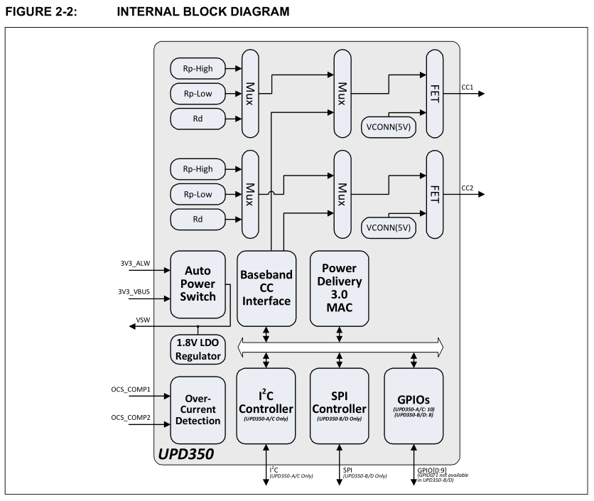
Clearly visible in this diagram is the Power Delivery 3.0 MAC which implements the actual USB-PD protocol while also providing an interface to the I2C or SPI controller. This can be thought of as equivalent to the MAC (medium access control) with Ethernet, or the USB (non-PD) MAC. The Baseband CC Interface is then the physical layer (PHY) that translates between the MAC and the analog front end that is connected to the CC line.
During all communication of USB-PD, the DFP is the bus master and thus initiates all communication. As mentioned, USB-PD is half-duplex, using only a single CC line for communication, which occurs at a baud rate of 300 kbps. CRC32 is used for error detection, with all messages encoded using 32-bit 4b/5b encoded biphase mark code (BMC), which is also known as differential Manchester encoding (DM).
The basic message format for USB-PD including a payload section is detailed in the USB-PD specification:
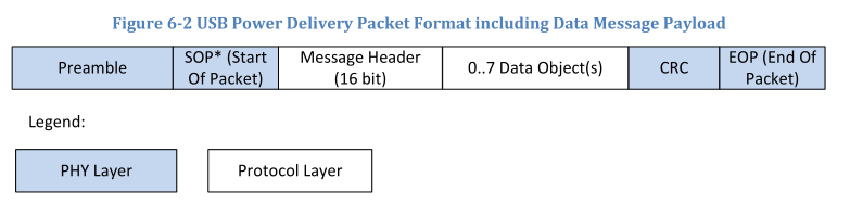
There are a number of different data object types:
- BIST Data Object (BDO) – Used for physical layer compliance testing.
- Power Data Object (PDO) – Exposes a source’s power capabilities or a sink’s power requirements.
- Request Data Object (RDO) – Used by a sink to request certain power settings from the source.
- Vendor Defined Data Object (VDO) – Convey vendor specific information.
- Battery Status Data Object (BSDO) – Conveys battery status information.
- Alert Data Object (ADO) – Indicate events occurring on the source or sink.
Generally, the DFP would send a list of its capabilities (source capability PDOs), which the UFP will then use to select a suitable option based upon its needs and send a request for this using an RDO data object message. This is however not the whole story, as due to the higher voltages and currents involved, some of these power levels require active “electronically marked” EMCA cables.
With great power
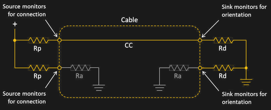
All USB-C cables are expected to support 20 V at 3 A for a total of 60 W. In order to be detected as capable of higher voltages and currents by the USB-PD controller, USB-C cables are required to contain a so-called e-marker chip which contains a vendor defined message (VDM) containing details on the cable and its capabilities.
This results in a slightly more involved wiring scheme than with a non-marked cable:
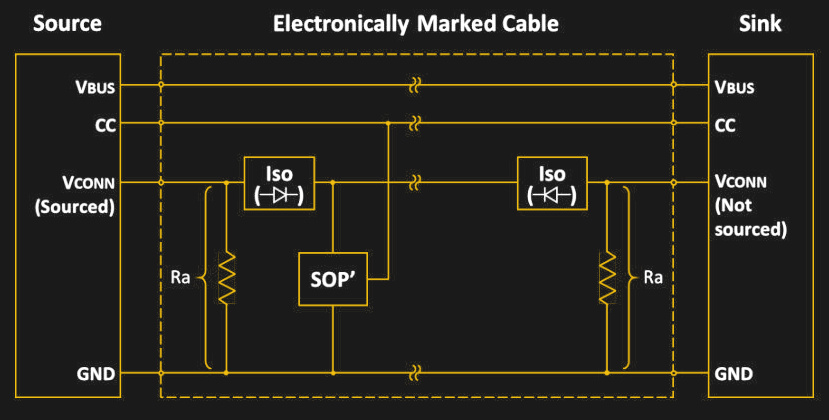
In this case the same CC signal line is used to query the chip embedded in the attached cable. If the USB-PD controller is satisfied that the cable satisfies the requirements for the required voltage and current settings, it will proceed with power levels beyond those for non-marked cables.
This becomes especially important with the R3.1 USB-PD standard, which increases voltages to a maximum of 48 V as part of fixed voltage EPR mode, while keeping the same maximum current of 5 A. As current is the defining factor in whether cables melt or not when drawing high power levels, this makes a lot of sense, but the increased voltage levels come with the risk of arcing, especially when plugging in or unplugging a USB-C cable.
In theory, with the higher voltages being firmly locked behind EMCA cables with newly designed USB-C connectors that have lengthened CC and Vbus pins, a disconnect event with active EPR voltages should be detectable in time to rapidly reduce the current and prevent hardware damage.
Comparing the different modes
So far we have looked primarily at the fixed voltage modes of USB-PD. These support a number of fixed voltages as the name suggests. For SPR these voltages are:
- 5 V
- 9 V
- 15 V
- 20 V
All of these can be selected with 3 A or 5 A current levels.
EPR adds the following voltages, all at 5 A:
- 28 V
- 36 V
- 48 V
For some purposes, these voltages may not be ideal, in which case the Programmable Power Supply (PPS) or Adjustable Voltage Supply (AVS) modes may be more suitable. The PPS mode can be used with SPR, following the rough voltage levels of the latter, but allowing for the voltage to be adjusted between 3.3 V and the SPR voltage level plus 1 or 2 V, in steps of 20 mV.
AVS mode does basically the same thing as PPS, only starting from 15 V as the lowest voltage level, ranging up to any of the three EPR voltages in steps of 100 mV. Which of these voltages are available in PPS or AVS mode works the same as with regular fixed voltage usage, in that the USB-PD controller determines the limits based on the detected hardware.
Universal Power Bus
In hindsight it’s both logical and perhaps somewhat absurd how a computer’s I/O connector that was originally designed to carry data to and from USB devices ended up morphing in what we have today in the form of USB-C and the USB-PD specification. Whether the R3.1 USB-PD specification forms truly the pinnacle of USB-PD remains to be seen.
With USB-C R3.1 EPR-capable cables now able to supply up to 240 W, one might think that this ought to be enough for charging any laptop today and in the future. Already at this point, EPR mode has brought new meaning to the term ‘hot-plugging’ when arcing is considered a concern by the USB-C specification. This makes it likely that perhaps the future of USB-PD may lead to new refinements that make the PPS and AVS modes easier to use, or adding new modes entirely that make setting a desired voltage and current even easier.
Now if only you could tell what a USB-C port on a device is capable of by looking at it :)


good article but i’m just here to point out that Joe Kim is the hero of hackaday!!
If Joe Kim is the artist that made the illustration to the article: Great Work! Please sign your work.
Oh yes, that’s Joe Kim’s work for sure!
If you want to see more, browse back through this category: https://hackaday.com/category/curated/original-art/
I feel stupid that I look at the artwork all the time and never noticed the artist. I searched found this as well: https://hackaday.io/project/12230-hackaday-illustrations .
My generation had Robert Tinney; yours has Joe Kim.
My wife claims that art is both ephemeral and eternal, and exists to answer its own questions; and that at any given day human technology is transitory and mostly forgettable; and that technology seldom has any questions and mostly just provides answers to stuff that nobody was asking.
As an engineer, I plead guilty as charged. I have decided that my retirement will consist of providing answers to questions that were never asked.
Although the current version of the USB-PD spec omits 12V support, an earlier version included that voltage, and some source devices can supply it. That’s a useful voltage in some applications because devices that are designed to run from automobile power often want it; leaving it out of newer versions of the spec was an unfortunate omission. Newer sources that support PPD can be asked to provide 12V.
I’ve been wondering for a while why a few of my USB-PD chargers don’t have 12v mode. Now I learn it’s because the official spec is just 5v, 9v, 15, 20v. They designed a multi voltage “universal” power supply system and skipped 12 volts. Surely nothing that consumes DC power in modern life requires 12 volts. Oh but they made sure to require 15 volts. Everyone knows you can’t rummage through a parts bin without finding 3 things that run on 15 volts!
Sigh…
Everything about modern USB screams design-by-committee.
Yea, why not just ask that one guy on the internet that has all the answers, instead of a group of engineers that spend many hours on finding the best possible solution for all the intended applications and use cases that are known to the different industries who want to implement and use the tech…
Were you there when this was decided? Did you actually read/hear why they came to this solution?
well, probably some of them wanted 12v, and some didn’t, and then others who wanted 17.54V Thus the output by committee..
It’s fairly obvious that it should have had 12v. Not quite so obvious – but what I would have liked :-) is 3.3V, which is the new 5v… :-)
I’d like to live in that universe of yours..
“finding the best solution”..
… I laughed, thanks for that
I wonder if the voltages were chosen in order to simplify charging of various batteries? 5V is good for a liPo pack, 15 for others? Getting a close voltage might eliminate the need for a robust charge regulator. A lot of our stuff needs a wall wart for charging more than for constant power.
That is so true!
Ask anyone who design circuits for automotive, you cannot expect the voltage to be 12V all the time.
It can be anywhere between 7 or 8V to all the way up to 14V even in normal cases. During fault condition, it can be negative (someone jump started wrong polarity) to 16V+ (battery boiling or suddenly disconnected) along with the usual spikes and brown outs.
Personally I think that USB-PD is a bit overcomplicated for what it is. Or the documentation could perhaps be a bit better.
Though, USB-PD has gotten fairly far, and honestly, the arching problem could probably be fixed if one of the pins in the connector were intentionally made a bit too short, so that it always unplugs first and thereby informing the system that the cable is getting unplugged. After all, if we rapidly pull out the cable, then even at 10 m/s, moving a single mm takes still 100µs, plenty of time to drop the voltage back down and greatly reduce arching, and any parasitic inductance in the cables is relatively tiny and shouldn’t under normal circumstances be too hard to deal with.
But to be fair here, USB-PD is maybe a bit too cluttered.
Though, at least they aren’t pinging the cable to figure out its rough length and then measure the voltage drop at a given current to work out the rough wire diameter and associated power loss per unit length of cable. So I can’t blame the USB-IF too harshly, but I at least think it might soon be time to start from scratch with some new peripheral bus standard that better caters to the needs thrown onto it.
No. But a voltage-sensitive sink device could monitor the received voltage and use PPD to get what it really wants after the voltage drop in the cable.
Lots of talk, no action. When are you going to step up and actually do something? This is the perfect website to present your ideas. Stop complaining and start innovating! I want to see articles from you on a better design. Get on it!
Simplest thing to do would be make “USB 4.0” a unique connector, perhaps with backwards compatible data and 5v – so all devices on it then end up being tolerant of whatever voltages it supplies – same way all your M2 and PCIe devices generally just use what the socket provides.. In many ways with how USB is going just making the next ‘USB’ connector a M2 compatible would make sense (presumably a M2 keying that has USB and PCI lanes concurrently for backwards compatibility)
This whole crazy situation of negotiation for power just doesn’t make sense, its so complex and really doesn’t need to be, if 12V at 5A is the high voltage line spec or 200V at 50A, really doesn’t matter (though probably something more sensible in the 12-24V range and handful of amps, as putting that much DC power through a connector means your laptop has to grow rather considerably) then every device getting connected either will run on those voltages natively or as most things do now anyway have its own buck/boost to get the voltages they actually need internally…
Basically every electronic thing more complex than a lightbulb and brushed motor ever will have power regulation onboard somewhere, to take whatever the supply voltage is and turn it to the logic voltage(s) needed, so negotiation for the ‘right’ power, with the cable having to have an IC in it to agree its up to the task is just bonkers – make the cables cheap and easily standardised by only supporting x amps and y volts on the power pin(s), while adding nothing to the cost of the devices as they need power regulation internally anyway!
So with your design, with no negotiation, high powered devices will crash a host that can’t supply the power. Or are you saying that all hosts must be capable of powering all devices? I can’t see how it’s possible to do what you say with a low power host like a microcontroller, it sure is not going to be able to power a spinning rust USB drive box.
IF it uses “USB 4” ports as the master not slave side than that port must be able to supply the spec, same as any spec ever, which is pretty trivial (especially if you pick a sane ‘high’ voltage and current), plus your low power microcontrollers generally are devices not masters if using USB so will be using supplied power, or they use an inter-circuit protocol like SPI i2C old school serial links etc to the other micros in the pile – USB is a bad choice for those things…
Also if the host device can’t supply enough it really shouldn’t bother the host at all, the connected devices might brown out but the host isn’t going to just die, what happens when you throw a USB hub (unpowered) and lots of devices on it – some/all of those devices won’t run, but the computer doesn’t (or at least really shouldn’t) care at all. (And the external devices not working is no different to what you have with the hideously complex negotiation stuff, if any step says no it doesn’t get what it needs, so doesn’t work..)
All adding the negotiation stuff really does is add more points of failure, for no meaningful gain…
Any serial device spec that doesn’t work with low powered microcontrollers is DOA.
And this “USB 4” simplified power concept works perfectly for them, in the same way current USB does, as the slave… Actually making them the master is also easier than negotiated bollocks – the power delivery is just a basic damn power bus same as always, nothing to do with the ‘low powered micro’ and you don’t waste 90% of the small micro implementing the PD negotiation and control!!
If you want a low powered micro to master the USB bus its power is simply supplied by by the standard power regulation circuit from its supply voltage, as is the peripheral needing this “USB 4” power, same as always one input voltage, simple buck/boosts for the rest of the required voltages whatever they may be, which for a micro is usually less than USB’s 5V anyway…
Yes. The evilness of the USB-IF rivals that of Sauron.
We’re all waiting for your work on an improvement. When can we expect a presentation?
When you’re done bootlicking them I suppose.
If you’re expecting them to participate in a standards process to get their better idea adopted you can wait approximately 20 years after they acquire the requisite 8-figures of bankroll.
Calm down though. Your preferred terrible connector is the standard and you don’t need to worry it won’t take over the world anymore. Instead you can wonder why half the time you use a charger you didn’t by your device doesn’t support it.
Taking bets here for the date of the first
1) USB cable firmware update pushed by windows update.
2) CVE related to a (production! No badusb!) USB cable.
I have been working on (chip-level) USB4 stuff at my pay-the-bills job, including PD and CC protocol magic.
The whole specs are a big mess. CVEs will come, be sure of that. Having an MCU on both ends of a cable is only good for one thing: selling MCUs for putting them on both ends of a cable.
And having an invisible way of putting your trojan horse into somebodies PC deliberately, as a slightly warm, or bulky cable end is no longer in any way surprising – its how they are meant to be…
Almost makes me wonder if Wireless tech is now more secure, which really shouldn’t be possible as it broadcasts, however sure it broadcasts but if its BT/2.4ghz its hopping around so much actually catching only one keyboard and enough of its data to be useful etc is actually some degree of work, the range is pretty low, so you have to hang around nearby… Where just dropping by and swapping some USB cables once and having that cable then do all the work for you…
No amount of hopping will help, even cheap-ish SDRs have enough bandwith to just capture everything in the 2.4GHz band.
The reason why cables are more secure is you actually have to touch most of them to get anything.Physical security matters!
With wireless, your range from your target is limited only by how big of an antenna you can afford.
Yes you can hopefully capture it all, but actually getting it all put together correctly so you can actually read useful data is a much harder proposition especially with any encryption and a crowded space – heck in really crowded space you might not pick up detectably enough of any one keyboard etc, as there is just too many devices crowded in that space at similar power levels to your distant antenna – lots of them will get lost in the noise, or be forced into hopping to parts of the band you can’t pick up as strongly for whatever reason.
And a really big antenna (presumably directional to help actually get just the targets you want) isn’t very easy to do subtly. Where getting access to swap cables, or getting their techs to swap cables for you – perhaps by sending them upgrades from ‘headoffice’ to install, or just intercepting the normal transit chain for a small substitution, and it just lasts, and won’t be easy to spot at all, heck how can we as consumers be at all sure our cable isn’t spying on us then?
I do agree cables should be better, as obviously they should – but a cable that is expected to contain enough smarts and carry enough data and power lines to do current or future USB specs as things are going… Just how are you going to tell the difference between one just doing its job and one with a much more nefarious purpose? And that ‘smart’ cable is therefore going to be a real bitch to find, if you ever do – not hard to have it read all the data through it and filter down to the bits you might actually want, then dump it in ways hard to detect, only takes fractions of a second to send a few data packets, in amongst a sea of legitimate ones, you might not even notice if you were watching the computer at the time…
And that doesn’t account for these smart cables being able to just outright own your device… Run that nice little script that turns you into part of botnet, ransomwares you etc… You want your devices to be auditable, reliable and predictable, and I really don’t see how putting little potentially hostile smart chips in everything (and worse then sealing them up in the cable so you can’t probe them non-destructively) is good for anything but selling overpriced cables…
OR that the way USB is going its a right pain for anybody that might just want to hack their USB cable up to attach to something else… Many a USB cable with a dud end has been reborn with application of solder and flux, quite possiblly now as a USB tether for that device with the broken port you are too cheap to replace, or the interconnect between that usb device you took apart and the rest of the project you are building…
great Post, thank you
does anyone saw already a power supply with EPR standard? can’t wait to have one single powersupply to charge, Smartphone, Gadgets, Powerbanks, Notebooks AND my E-Bike :)
Surely a simple open collector, one wire serial bus with say 9600 baud over 5 meters of shielded cable wouldn’t have worked for sending packets with information content of “give me 20V, 3 amps” and “yay, here you go” or “no, I only have 5V, 1A”. That way even the simplest microcontroller could have interfaced PD. But no, let’s use some fancy encoding to require custom silicon for this… What a waste of resources.
Just like how they did with the original version of the USB spec. The low-speed spec could have easily been a simple UART interface so that any device can easily be upgraded to connect via USB at least with low speeds. Instead they gave rise to a whole industry of USB to serial interface chips which shouldn’t have been needed in the first place for quite some applications.
Also don’t forget about how they deal with the USB Vendor IDs, that has been covered by Hackaday already.
I realize how an industry association works, that it needs money, and members look mostly at their own benefit only, but the USB IF is among the worst of them.
erm, where would you put this simple link? You can’t use the data lines, as switching from this format to a high-speed, low volatge one is anything but simple without custom silicon.
So you’d need an extra pin.
For PD, there’s nothing wrong with the extra CC pin, it’s just that a simple one wire UART would have been fine for communication to which every existing and the most simplest micros can interface. You don’t need Manchester encoding for low speed communication over a few meters of internally and externally shielded cable.
Instead, now you require MCUs with dedicated USB PD silicon and in the case of ST for instance a binary blob of firmware for it. All that for what can be communicated over a few bytes worth of data.
If you meant the imaginary low-speed USB UART interface that they should have implemented: sure, that would require support silicon in the host controller for switching over the data lines and an actual UART. But that’s probably 1% more die area on the host side which would have allowed any and all micros on the device side to have low speed USB support without any extra costs.
I totally agree!
I’ve fiddled a bit with PD enabled STM32. The protocol is more complicated than basic USB2. Terrible ST firmware with binary blob PD library adds to the mess.
I really don’t see a reason for it to be so complicated. It’s only negotiating voltage and current not guiding rockets to the moon!
Noting that there have been other articles on various PD protocols (Apple, Qualcomm et al.), I think it’s fair to ask whether anybody has ever designed an affordable piece of testgear which can monitor and report on the protocol attempted by an arbitrary USB device being plugged into an arbitrary USB port.