There was a time when people like us might own a tube tester and even if you didn’t, you probably knew which drug store had a tube testing machine you could use for free. We aren’t sure that’s a testament to capitalistic ingenuity or an inditement of tube reliability — maybe both. As [Usagi] has been working on some tube-based projects, he decided he needed a tester so he built one. You can see the results in the video, below.
The tester only uses 24V, but for the projects he’s building, that’s close to the operation in the real circuits. He does have a traditional tube tester, but it uses 100s of volts which is a different operating regime.
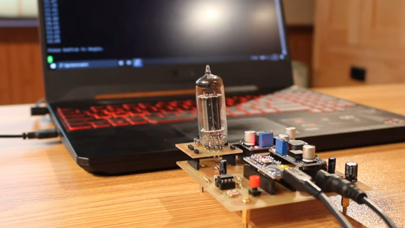
The bulk of the circuit is creating the voltages required, including a 555 charge pump to generate around -10V. The tube is wired up in a particular configuration and the Arduino makes a few measurements while changing the operating bias conditions. The converter goes through a voltage divider so the maximum 24 volts won’t overload the Arduino.
Grabbing the data into a spreadsheet allowed some curve tracing which looked useful for matching. However, as [Usagi] points out, the tester is very specific to his application. He has plans to maybe make a more general-purpose tube tester.
One of the problems with a truly general-purpose tube tester is connecting to the different pinouts. Punched cards offered one answer. If you don’t remember tube testers in drug stores, you might find that TV repair, at one time, was a big business.


Can this be altered to allow 12v valves to be tested ? Thanks for a great project. Dennis
Thank you!
And it absolutely could! It would actually even simplify it a bit because you could use a 12V wall wart and ditch one of the buck regulators. Then, it’s just a matter of changing the resistors for the voltage divider for the Arduino and double checking that the grid is still behaving like it should. All in all, it would be a super simple change!
Thank you for your reply. Once bench is clear next week will certainly look at this as want to build a small receiver or a transceiver if I have enough from what I have. Do you have a link for project details. Thanks Dennis
Fine for those miniature tubes. How about those low voltage full sized big honkin’ tubes?
It works great for 7- and 9-pin tubes, but old Octal tubes and larger would be a little tough as they’re physically larger than the entire tester, haha.
Tubes could be tested because they plugged in. I’m not sure it’s completely that tubes failed.
Anyone could go to a drugstore and test their tubes. They say the drugstore testers helped the profess, skewing away from “good”. And that was the limit of what most people could do.
When transistors arrived, so did transistor tester projects. Some of it made sense, a need to get some information about unmarked transistors from Poly-Paks, or try to select some with better specs when they were limited.
But some of it seemed a holdover from tubes, “we had tube testers, we should test transistors”. Most of what you need is in in a DMM or VOM, is it good or bad, rather than “weak”
Transistors, once they became common enough, had the benefit of being considerably cheaper than tubes too, so it just made more sense to replace a questionable transistor than to test it.
Granted, for the 6AU6 tube that I happen to use the most, I’ve got about 1100 in my collection, so it’s definitely easier to just replace a questionable tube than test it, but I had a string of tough luck and ran into three bad tubes in rapid succession, which sent me down a rabbit hole of my testing my circuit instead of looking at the tubes, because I’ve never had three go bad so close to each other before. (One had a hairline fracture and had gone to air, another was just really weak, and the third actually had a short in it.)
The good part of the tester I built here was I could see just how weak the weak tube was instead of just guessing that it might be weak. Having actual data to compare against known good stuff is so satisfying it made the whole project worth it!
>> Granted, for the 6AU6 tube that I happen to use the most, I’ve got about 1100 in my collection…
Ahh, now I know who bought them all! ;) jk lol
That is a very, very useful, and thankfully very plentiful, pentode. I find myself using those or 12AU6 quite often, depending on the heater voltages of other tubes in the circuit or device. That’s kind of amazing they’ll work down to such low plate voltage!
Another miniature I really like, probably for nostalgic reasons, is the 6C4, a 7-pin medium-mu triode. I find it in many instruments from the 1960s, and maybe it’s just my personal experience, but it’ll take a LOT of abuse. No idea whether it’d ever work with only +24 V to the plate, though.
It was an interesting era to be alive.
On one hand, some designers would make push-pull output stages with minimal feedback and “wildly imbalanced” Vbe and hFE values on the two transistors would result in audible distortion. The manufacturers wanted to ship anything that wasn’t technically an open circuit or short circuit so datasheet specifications were … a little wider than you’d see on a 2021 transistor datasheet, things are a little more constrained now and more likely to match out of the box, but not so much in 1970. So you could pay a mfgr a lot of money for “matched pair” packages of two transistors for like 10x the cost of one, or you could buy the rat shack qty 25 “best of luck to you” generic NPN transistor bulkpack and spend some labor making your own matched pairs.
On the other hand there were designers who were, like, flicking on a LED, there’s not a major difference between a 2n3904 and a 2n5089. Both of them have a Vce WAY way WAY over 5 volts, both have an Ic-max that laughs at LED levels of current. The TTL output doesn’t really care if its sinking a hundredth of 20 mA or a four hundredth of 20 mA so regardless of exact transistor beta value it’ll be “good enough” its going to sink a lot less than old fashioned TTL max of 10 mA or 16 or whatever it was back when there was only TTL and not a dozen extended logic families… So there were entire databooks on the topic of which transistors were “mighty similar” to each other enough to make it worth considering a substitution. Technically the ‘5089 is a weak signal RF amp low level analog marketed beastie whereas the 3904 was more of a generic switch per the marketing, but often enough if you’re just lighting up a LED substitution will work and no need to plug into a test set to measure and match the hFE or whatever. I have not compared the two datasheets in detail but they seem close enough to substitute for a LED driver, but I would not try that with a ham radio transmitter or a mic preamp or anything pushing the limits of tech at that time without extensive review.
The real meta issue is tubes were/are expendable with a low MTBF and its expected you’ll be replacing them on a regular basis, whereas “Transistors are forever” so unless you do something dumb with overheating or static electricity you never replace them making a tester kinda overkill for most folks, they just are not going to use the tester very often, compared to a tube tester that’ll get a workout.
Hmm. Interesting project. I have a TV-7 tester that I bought about 35 years ago for $50, before the audiophools drove up the price. It would be an interesting project to automate it, but unfortunately, that would send its resale value crashing. Now, when you can find them, they go for about $800. Maybe a bad one could be bought cheaply so you’d have the switches and sockets… I’ll start looking…
I have a TV-7 as well. Of the dozen or so testers I have owned, it is the one I always kept. I have been following the development of the mu-tracer but will probably use one in addition to the classic. There are plenty of ~100USD tube testers out there if you just want a case, sockets, and switches :)
As a tube amp enthusiast, and someone who has all sorts of random tubes in boxes with no way to test them, this is so awesome. I can’t wait to see a version that could test at full voltages as I would not be surprised that you see a different response from even the tubes you are using when used at full voltage. My question to you would be, considering what we can do with computers now, are there any other ways we might want to test tubes and graph them that was not possible back when we literally had to go step by step and draw thing on a graph paper. Personally I would pay for a kit where I could test my range of tubes. It would also be cool if there was an easy way to hit a switch and triode strap a pentode to get both curves. Great video and great work, such a cool project.
Usagi Electric, is there a list of the exact parts you used for this? Trying to recreate for fun but not sure if I could use 1/2 W resistors or 1W, specific caps and diodes, etc. What do you recommend? Thanks!