We are big fans of the little desktop magnetic levitation setups that float a small object on a magnet. As [3D Printed Life] points out, they look like magic. He was surprised that the commercial units use analog electronics. He decided to build a digital version but didn’t know what he was getting into. He details his journey in the video you can see below.
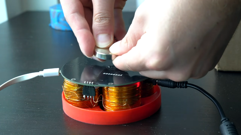
Along with a custom control board, he decided to wind his own electromagnets. After finding that tedious he built a simple coil winder to automate some of the work.
If you have ever struggled to find the sweet spot for the magnet on one of these, his first problem was completely predictable. He lost control of the magnet which slammed against the PCB and either physically or electrically damaged the magnetic sensor. After that, he installed a shield to prevent the magnet from directly contacting the board.
The first iteration didn’t work as expected and the magnetic platform kept flipping over. He eventually found a teardown of a commercial unit that showed he needed more stabilizing magnets around the outside of the electromagnets. He also didn’t have the electromagnets set for reversing the polarity.
Solving the polarity problems required repurposing an H bridge circuit that you usually see for motor control. A new board fried after a little testing. Then there was a mechanical failure.
Once the hardware was working, the software posed its own problems. A PID controller wasn’t stable enough. He also tried filtering inputs and adding some other corrections. The platform would float a little but eventually will crash to the electromagnets.
He didn’t get a final working build but he’s hoping someone will be able to give him some advice on getting it working. We figured someone who reads Hackaday has certainly built one of these before and might be able to help.
Maybe a change in axis would be easier. There are several older projects that might provide some inspiration.


Maxwell and Hamilton(ion) say it is unstable. All you need is a magnetic monople.
Stable magnetic levitation ( or suspension ) is a good example of what a few opamps can do cheaply vs a lot of digital electronics / code.
Indeed. An inverted pendulum can be made with just four opamps.
I think that is true, and using PID may do more harm than good.
Levitation can also be done passively, I have read. An off resonant Inductor/Capacitor tank circuit driven with AC gets closer to the resonant frequency when the iron is further away from the work coil, which causes it to just hang. I’d love to see this done. I’ve seen passive eddy current ‘levitation’ (it bounced around) of a ring at 50Hz.
You can do PID in analog easily. Multiplying by a constant, integrating, and differentiating is what op-amps do so well. Some digital pots for setting the values will make a tunable PID with a micro that monitors position. That is a nice project.
I’m honored to be the biggest failure of the week :) Lesson learned, sometimes avoiding analog is way harder than it may seem!
AFAIK, you haven’t failed yet, just a temporary setback. Failure is when you give up altogether
Sometimes failure is stubbornly pressing on with a task that should be abandoned. Probably not the case here, but worth bearing in mind for many of us I suspect.
Who decides when a task should be abandoned? Asking for a friend.
By that definition all works of art are failures
Conversely, he has been perfectly successful at making a chaotic oscillator.
Could be a single magnetic sensor isn’t enough. Have you heard of pilot induced oscillation? That’s where an airplane pilot over corrects for a movement of the plane so the plane goes too far the other way. Then the pilot makes too large of an opposite control input.
Back and forth, getting worse and worse until the plane breaks and crashes, or fails to fly properly and crashes. The key to surviving PIO is often to simply get hands and feet off the controls and let the plane settle itself.
That’s what it looks like your digital control system is doing, it’s overcorrecting and making the magnet flip out instead of damping the oscillation.
Aircraft engineers went to a lot of effort to make aircraft naturally stable, but that made them less able to make rapid maneuvers. When electronic controls were invented that were fast enough, it became possible to build aircraft that were not naturally stable. They’re constantly wanting to go sideways or pitch up or try to spin around and go backwards. Only the constant twiddling of the control surfaces by the computers keeps them going nose first. The pilot’s movements of the control stick and rudder pedals are directions to the flight computer to allow the airplane’s instability to be allowed to turn the plane in the desired direction. I wouldn’t be surprised to find that in a plane like an F-18 if a pilot wanted to do some PIO, the control computers wouldn’t allow it.
PID control loops should be able to handle it and effectively dampen the PIO-like-effect. It’s just a matter of getting the logic and tuning right for the inputs. Drone controllers are basically doing the same exact thing here, and software has evolved quite a bit. In the early days, they used to flip and go bonkers just like the magnets in this video. But after hundreds (thousands?) of iterations, the open source controller software can pretty much make any drone rock solid in most conditions. It was neat to see him add a low pass filter, too. That’s something controller software uses as well, to clean up the signal and ignore motor vibrations that would freak out older versions of the code.
This system has more degrees of freedom than the control circuit can handle. In other words, the set of equations that describe this system has more than one valid solution. An additional boundary condition can be introduced by carefully shaping the magnetic field of the coils or simply by putting the levitated magnet in a glass jar.
A pid is only as good as the tuning and the input. You can build two identical systems with the same pid values and then move the sensor 1mm over on one, and get totally different behavior between the two.
One solution is adaptive pid, but that requires the system to be semi tuned and stable which you seem to have it it works for some period of time. It’ll then adjust the algorithm to keep it stable, but there’s a lot of black magic involved there.
Hmmm. An Arduino Nano type thing + digital pots + analog PID. How to optimize without all the analysis? It seems like a perfect job for a Simplex algorithm, which would be a snap for an ATMega328. That would be a very neat project. I would use the vector simplex optimization method, not the linear programming the search engines will pull up. http://195.134.76.37/applets/AppletSimplex/Appl_Simplex2.html and https://en.wikipedia.org/wiki/Nelder%E2%80%93Mead_method
Why would you use (shudder) digital potentiometers and opamps for the control loop? The microcontroller can do the same loop, with the added benefit of better filters, gain scheduling, and other tricks that are much harder to do analog.
With digital control, you can try to use the same automatic loop tuning algorithms.
It’s not quite clear to me how the current control loop works, considering it needs to control 4 coils and several degrees of freedom of the magnet, but what I did in the past, with a variation on the inverted pendulum, was cascading loops, such that each loop controls a derivative of the process. Instead of trying to control the position directly, the position loop output is the setpoint for the next controller, which is the speed control loop, which, in my case, generated the setpoint for the torque (motor current) control loop. Each successive control loop runs at a higher rate than the previous one.
This way, you prevent the situation where there is a position error, but the object is already moving so fast it would overshoot the desired position without adding any more energy, and a single loop would continue to add energy. Now theoretically, the derivative term should solve this, but in practice it’s very difficult to get this “just right”, especially in a noisy environment where a high derivative gain would greatly amplify this noise.
Basically because the OP says using a digital PID was not working. The analog circuit is probably faster here. Th update-rate is basically the gain-bandwidth product for the circuit which can be several MHz.
Earnshaw theorem from Wikipedia:
Earnshaw’s theorem applies to classical inverse-square law forces (electric and gravitational) and also to the magnetic forces of permanent magnets, if the magnets are hard (the magnets do not vary in strength with external fields). Earnshaw’s theorem forbids magnetic levitation in many common situations.
If the materials are not hard, Braunbeck’s extension shows that materials with relative magnetic permeability greater than one (paramagnetism) are further destabilising, but materials with a permeability less than one (diamagnetic materials) permit stable configurations.
You should watch this for some great insights & history:
https://aeon.co/videos/in-this-1975-lecture-the-maglev-trains-inventor-deconstructs-his-ingenious-design
Control theory has one easy rule of thumb: if a small wobble gets bigger and bigger, the delay between reading the position and responding to the reading is too long.
That’s why many control systems are analog: analog is faster than digital, often by orders of magnitude.
Digital control belongs to the branch called ‘modern control theory’, which rests on the assumption that you have time to do plenty of numerical analysis between reading and responding. The Kalman filter predicts the next reading from what it knows before taking the reading, then compares the reading to the prediction. It changes the controls until the average difference is zero (equal distribution of predictions above and below the readings), then tunes itself to make the average magnitude of the differences as small as possible. The Madgwick filter is a simplified version that skips the statistical analysis and tunes a ratio of ‘correction relative to the prediction’ and ‘correction due to the current reading’ to get the best results. The ‘complementary filter’ is a trivial reduction of the Madgwick that just chooses a ratio and sticks with that.
But in all cases, the control system has to be faster than the thing it controls.
For the system shown above, I’d guess that the major source of delay lives in the electromagnets. They’re large, which means they’ll have fairly high reactance (tendency to resist changes in current). It also looks like the system uses PWM to control them, and PWM trades speed for resolution. Putting the two together, there’s a good chance that the magnetic field felt by the target is a nonlinear function of the PWM duty cycle.
You can probably get better control by switching to pulse density modulation (PDM): find a pulse width that’s much narrower than the period of the floating magnet’s wobble (100x would be great), then measure the current that flows through the coils during (and after) such a pulse. You want the best tradeoff of minimum time and maximum current. That pulse will give you a known and consistent control output, and you can vary the strength of the output by changing the delay between pulses. Instead of doing a 50% duty cycle as 50ms-ON/50ms-OFF, you’d get 50 @ 1ms-ON/1ms-OFF (assuming a 1ms pulse was the best time/current value). The floating magnet can move 50 times as far in the PWM case as it can in the PDM case.
That’s another benefit of analog in this case: changing the current through an inductor by a small amount is much faster and easier than bang-bang on/off control. You might consider adding large capacitors in parallel with your electromagnets to smooth the pulses to a more continuous form.
Once you have the control system response timing fast enough to be useful, you can start testing to decide if a single Hall effect sensor gives you enough information for good control.
I think there is more to it in this situation. Using a uC to close the control loop is never an easy thing.
Never underestimate the “MIPS” of a number of OP-AMPS. replacing them with a lower end or perhaps a higher end uC just might not be enough.
Your most often better off closing the loop as analog and having a uC periodically adjust some parameters without the loop being in any way dependent on the uC.
So, if Godzilla ate Magneto,
would he become a magnetic leviathan?
I have a simiar project under way – again with limited success so far. To start with and to learn from I bought one of the DIY kits from China and after a lot of tweaking finally made it work. Adjustment of the zeroing pots is very critical, and I used a couple of 12V 6W car buls in series with each pair of coils to visualise the control currents.
My version uses op amps to amplify outputs from XYZ Hall sensors, then into an Arduino Micro to provide PID capability and PWM refernce voltages for a pair of dual H bridge drivers (MTS2916A from Microchip). Shaping of the magnetic field appears to be critical to success, as well as positioning of the Hall sensors. Work in progress!!
I have a simiar project under way – again with limited success so far. To start with and to learn from I bought one of the DIY kits from China and after a lot of tweaking finally made it work. Adjustment of the zeroing pots is very critical, and I used a couple of 12V 6W car buls in series with each pair of coils to visualise the control currents.
My version uses op amps to amplify outputs from XYZ Hall sensors, then into an Arduino Micro to provide PID capability and PWM refernce voltages for a pair of dual H bridge drivers (MTS2916A from Microchip). Shaping of the magnetic field appears to be critical to success, as well as positioning of the Hall sensors.
Hello Peter, What have you done with my machine? XD
I bought two of the DIY kits from China too, but none of them work properly.
You can feel that the coils work and are repelling the magnet, but it always flies sideways. I tried every possible adjustment on the potentiometers, but it didn’t work.
Could you help me?