When it comes to innovation in FDM 3D printing, there doesn’t seem to be much room left to move the needle. Pretty much everything about filament printing has been reduced to practice, with more or less every assembly available off the shelf. Even the business end — the extruder — is so optimized that there’s not much room left for innovation.
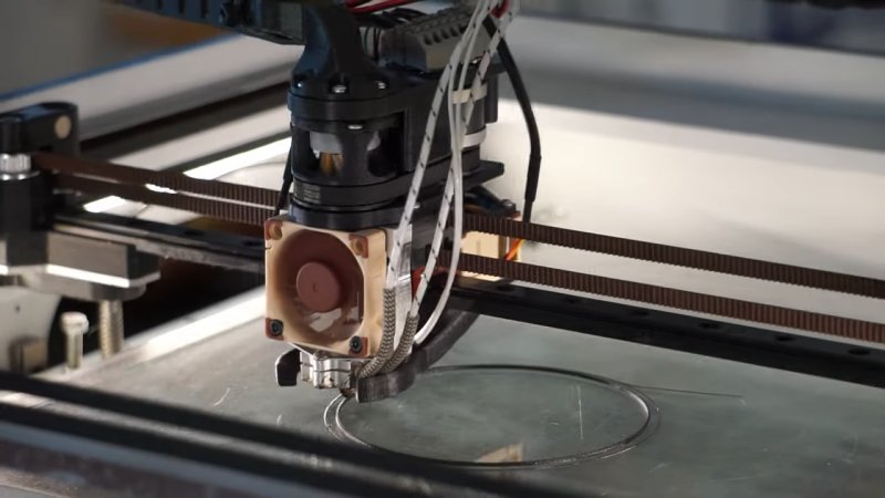
Or is there? The way [David Leitner] sees it, there is, which is why he built this rolling-screw extruder (if you can get to the Thingiverse link, [David] cross-posted on reddit, too). Standard extruders work on the pinch-roller principle, where the relatively soft filament is fed past a spring-loaded gear attached to a stepper motor. The stepper rotates the gear, which either advances the filament into or retracts it from the hot end. [David]’s design instead uses a trio of threaded rods mounted between two rings. The rods are at an angle relative to the central axis of the rings, forming a passage that’s just the right size for the filament to fit in. When the rings spin, the threads on the rods engage with the filament, gripping it around its whole circumference and advancing or retracting it depending on which way it’s spinning. The video below shows it working; we have to admit it’s pretty mesmerizing to watch.
[David] himself admits there’s not much advantage to it, perhaps other than a lower tendency to skip since the force is spread over the entire surface of the filament rather than just a small pinch point. Regardless, we like the kind of thinking that leads to something like this, and we’ll bet there are probably unseen benefits to it. And maybe the extruder actually is a place for innovation after all; witness this modular nozzle swapping system.
Thanks again to [BaldPower] for the tip.


Another advantage: it’s about the coolest looking extruder I’ve ever seen.
Also, it’s probably a lot easier to visually monitor extrusion rates.
It looks to me there are few more benefits. It must be better for flexible filament, also It does not require a reduction gear, but if you add one, the weaker motor can be used and greater precision can be achieved.
I’m not sure I understand the logic of adding another gear. It already is belt driven. Can the pulley on the motor side of the belt be made smaller? Or can the extruder side be made larger? Wouldn’t that have the same effect without adding any more complexity?
Reddit link seems to be pointing to thingiverse.
With 8 bearings in the extruder I wonder what would be the extra weight compared to say e3d titan
I am pretty sure that the last time this design came up (on reddit probably) somebody commented that there was a commercially version available.
yep; a Fuselab 3dprinter:
https://youtu.be/OVhw3XlrDuY
https://youtu.be/kqhjd5cdJPU
and the Reddit link is:
https://www.reddit.com/r/3Dprinting/comments/nowr6v/i_made_a_silly_extruder_works_like_a_charm
Maybe using piezoelectric actuators with a hole to walk the filament in and out of the work area.
https://www.pi-usa.us/fileadmin/user_upload/pi_us/files/catalogs/PI_Piezoelectric_Actuators_Catalog.pdf
Very cool. I have wondered if such solid-state actuators existed and could be used in this context.
I had that idea some time ago but quickly found out that piezoelectric motors are basically unobtainium for makers :-(
Great design! Looking forward to making one for a bowden extruder and having it stationary.
Could this be done with a hollow shaft motor that has the inner part of the shaft threaded? Seems like it could be thinned and lightened bu quite a lot that way…
That does sound interesting.
It would certainly be simpler mechanically. I like that.
I’m thinking probably not though.
The first problem that came to mind was how to unclog it. I guess you would have to disassemble the motor and throw the shaft in the oven.
As I thought that one through a bigger problem came to mind. A screw can impart two different motions on the filament. It can cut groves into the filament, sucking it down or pushing it back up as it goes depending on direction. Or it can just twist the filament.
Multiple screws on different sides of the filament will cancel one another’s twisting motion resulting in only the desired up/down movement. I think a single screw, either on one side or completely surrounding the filament like you propose would tend more to just twist the filament.
But that’s just my thoughts. It would be great to see an article up here where someone tried it to be sure!
I’d love to see it as well. Clogging can be solved with some thermal management. I would expect that a contra-rotating screw could be used axially.
Stack 2 hollow-shaft pancake motors with opposite threading. You could cancel twist and prevent backlash imho.
i had a similar idea but i have neither the tools nor the time to try. hollow threaded tube driven by a hydraulic motor.
the fluid could be used as dual purpose cooling and mechanical transmission to make the extruder lighter since the pump and cooling could be somewhere else. something like a reverse bowden combining the advantages of both DD and bowden. probably would be a nightmare do build and design but could be pretty cool if it works.
I was thinking to use the extruder in the article, just with an axially mounted stepper motor with a hollow shaft to route the filament down to the extruder. This gets rid of the belt and pulleys altogether.
I think part of the design is that the whole system is balanced over the support rod. If you put the stepper on the same side, that is putting a lot of torque on the supports. This design is only increasing the mass that needs to be supported, while balancing the head.
No, because a hollow threaded tube rotating around the filament would also impart a strong rotating (drag) force on the filament, not just a thrust force. Remember screws are just wound up inclined planes. The reason the design in the post works is because it’s a ROLLING screw extruder. The threaded rollers are rotating against the filament, such that there is not a rotational force on the filament but only a thrust force
Reminiscent of the extruder mechanism in the 3D Doodler pen.
That angle of the threaded rods angle reminds me a lot of that mechanism in hand-cranked pencil sharpeners. Pretty slick.
More moving parts -> worse, wont beat remote extruder.
Double duty as a lidar as well? :-)
Those that do not know their history are doomed to repeat it.
Screw extruders were quite common in the early RepRap days. A bit of googling gets me this page:
https://reprap.org/wiki/Nophead%27s_Extruder_Tweaks
Which is [NopHead’s] improved version, but is at least still a live page with decent pictures of the internals.
just because the word thread appear in the description doesn’t mean its the same thing. the link you posted is basically the grandfather of modern extruder. what he did here has no resemblance to it whatsoever. the whole advantage is to have 360° grip applied instead of one-sided teeth or threads.
Seems like it would be more tolerant of variations in the filament. Good if you are making your own.
Another take on the same concept:
https://reprap.org/forum/read.php?424,883786
Looks neat. I don’t get how this operates tho. Is the shaft spinning the rollers? Or threading the filament?
Its kinda neat, but I think the ‘use’ that keeps being repeated is over-stated. Anyone who has used a 3d printer and looked at the filament after the extruder knows the contact area isn’t ‘small’. The filament is round and the 2 gears on a standard one are curved around that, the contact area is across a large area.
This new one from the description (and its hard to see in the designs presented) surrounds a circular cross section with 3 sets of circular threads. So the contact area wouldn’t be as advertised ‘around the entire circumference’ but on 3 contact patches biting in to some depth.
Over several articles on different sites I haven’t seen anyone even doing testing to show the hypothetical skipping resistance. It wouldn’t be relatively easy to do simply by measuring the maximum flow for various temperatures that the different extruders can push through.
I suspect that. If you look at the filament, you will see thread impressions all around, as the screws rotates around the filament, which would make it look like full contact. But I agree it isn’t full contract.
ideas:
-use a thinner stepper with a hollow shaft to run filament through.
-use 1 or 2 paper cutting disks so that the package becomes thinner overall.