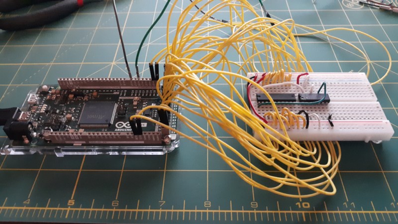
When it comes to electronic design, breadboarding a circuit is the fun part — the creative juices flow, parts come and go, jumpers build into a tangled mess, but it’s all worth it when the circuit finally comes to life. Then comes the “What have I done?” phase, where you’ve got to backtrack through the circuit to document exactly how you built it. If only there was a better way.
Thanks to [Nick Bild], there is, in the form of the “Schematic-o-matic”, which aims to automate the breadboard documentation process. The trick is using a breadboard where each bus bar is connected to an IO pin on an Arduino Due. A program runs through each point on the breadboard, running a continuity test to see if there’s a jumper connecting them. A Python program then uses the connection list, along with some basic information about where components are plugged into the board, to generate a KiCad schematic.
[Nick] admits the schematics are crude at this point, and that it’s a bit inconvenient to remove some components, like ICs, from the breadboard first to prevent false readings. But this seems like one of those things where getting 80% of the work done automatically and worrying about the rest later is a big win. Plus, we can see a path forward to automatic IC probing, and even measurement of passive components too. But even as it is, it’s a great tool.


Rookie mistake. I always draw my schematic /before/ I build the board.
how else can you do it??
Gosh, how wonderful Andrew. Everything you do obviously always works first time. I can’t wait to stop being a rookie.
Woosh
Yes, I do it the same way. 1st plan an design the circuit, then test it on the breadboard and only document changes to the plan.
Yes but the idea is neat, have to admit. By the way I always draw the schematic first too.
I do both, first have a general schematic, and if I’m not sure or add stuff from other schematics I end up trying it out and experiment on the breadboard first then incorporate the final results into the schematic. Throwing sections together from different sources, datasheets etc I often skip the schematic stage and go straight to breadboard. I often use parts that are not in the CAD so I have to draw them first. But if the part I’m trying isn’t going to be used, or try 10 different parts (ie 20-32+ pin ICs), it adds up quickly in drawing them.
I wonder if this would work by passing a very low voltage, like 200mV, too low to overcome the chips’ forward voltage
So this is basicaly the same thing but reversed:
https://hackaday.com/2021/06/23/silicon-jumpers-make-this-wire-free-breadboard-programmable/
There was also that one guy who was building an analog mux breadboard that would make the connections according to the schematic you drew.
Which is the same task in reverse.
They should combine those two projects so we get circuits that design themselves!
You want Skynet?
Because that is how you get Skynet. B^)
God forbid if you ever need to run a 12V or -5V rail onto the bread board. :P
The connections map is created while the circuit is powered off.
Really cool as a proof of concept. Probably still not worth the time.
Anyone else think it should be called the Schemat-inator?
It needs a Self Destruct button.
the same, but with the ability to measure discrete passive components. https://dspace.mit.edu/handle/1721.1/105988?show=full