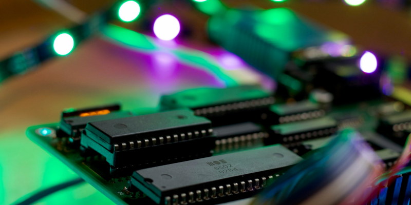
We can still remember when the WS2812 LED first came into our consciousness, way back in the mists of time. The timing diagrams in the datasheet-of-questionable-veracity made it sound quite tricky, with tight timing tolerances and essentially a high-speed two-bit PWM data protocol at 500 kHz. It was a challenge to bit-bang with an ATtiny85 back then, but there’s no way something as old and crusty as an Apple II would be up to snuff, right?
[Anders Nielsen] took up the challenge of getting the venerable 6502 processor to drive Neopixels and won! After all, if the chip is good enough for Bender and the Terminator T-800, it should be able to blink some colored LEDs, right? The secret sauce is shift registers!
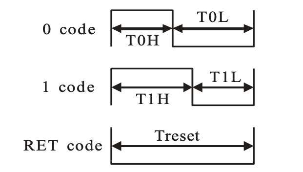 Specifically, [Anders] abuses the 74LS165 parallel-in, serial-out shift register for his dirty work. Instead of bit-banging the WS2812’s “long high is a 1, short high is a 0” signal directly, the first few bits of the shift register are hard-wired to VCC and the last few to GND.
The bits in the middle determine if the pulse shifted out is long or short, and they’re set by the 6502, through a 6522 VIA chip, just like the Apple II would have. Clocking the data out of the shift register handles the timing-critical stuff. Very clever!
Video below the break.


i don’t understand “a challenge to bit-bang with an attiny85”, it’s either possible or it isn’t? is this a reference to the extreme poverty of i/o peripherals on attiny (vs pic)?
none of the common i/o peripherals on almost any mcu is a good fit for WS2812
I would argue against that:
I use the SPI port on a TI TM4C1294 in mode 3 (phase 1 clock 1) at a bit rate of 2.5MBit – each bit is 400ns long. Then for each high bit I send a 110, for each loww bit I send a 100. shift all those 3 bit “wsbits” into your output stream and the WS doesnt mind 800/400 timing as opposed to the ridiculous specs in the datasheet (do note that my method is within the ±tolerances specified in the datasheet)
Here’s some crappy code I threw together, not sure if it is descriptive enough by itself or good, but I recall it working:
ws_time+=0.01;
ws_r=255*cos(ws_time);
ws_g=255*cos(2*PI/3 + ws_time);
ws_b=255*cos(4*PI/3 + ws_time);
for(int i=0; i<NUM_LED; i++)
{
//create intensity map
//intensity[i]=(255*i)/NUM_LED;
intensity[i]=64+64*sin(5*ws_time+2*PI*i/(NUM_LED/2));
//modulate colour by intensity and encode as GRB
GRB_data=(((ws_g*intensity[i])&0xFF00)<>8);
//GRB_data=0x00000001;
//encode to send out spi port
for(int ii=0; ii<3; ii++)
{
uint32_t wstemp;
uint8_t* wschunkin=(uint8_t*)&GRB_data;
uint8_t* wschunkout=(uint8_t*)&wstemp;
wstemp=wsencode(wschunkin[2-ii]);
out_data[i*9+ii*3]=wschunkout[2];
out_data[i*9+ii*3+1]=wschunkout[1];
out_data[i*9+ii*3+2]=wschunkout[0];
}
}
Neat. This gave me another thought – why not utilize slave SPI?
Using a single timer and two compare units to output 33% / 66% on-time PWM which are run through a SPDT (quick search turned up WAS3157B-6/TR, a 5 ct part), controlled via MISO. That way, all kinds of duty cycles are accessible and the need for bit encoding is removed.
https://youtu.be/wBcLXBo2I78
I posted a comment about this with c code and it might be censured, or stuck in moderation, i dont know.
anyways, I use the SPI port in mode 3 at 2.5Mbit, clock out 110 or 100 for 800ns/400ns “wsbits”, much easier on the CPU to encode the data and then load up the SPI FIFO and keep it full than trying to clock out the data in pure software.
It’s easy when your favorite uC OS can do it fine.
It’s difficult when you have o revert to writing in in C as the OS is too slow.
It’s a challenge when you have to revert to assembly when even C is to slow.
So it’s more than weather it’s “possible” or not. It’s about what time, effort or skill level is required to achieve it.
It’s not possible to get the timings right enough to bit-bang on a stock 8 MHz ATtiny in C, or at least tricky enough that I couldn’t do it — the “if” branch was a killer. There were some clever hacks using the SPI/UARTs as raw bitstreams, which is almost exactly the same thing as what’s happening here, but less flexible: an internal shift register is filled and shifted out.
The trick to bitbanging was to drop down to assembler and do the tight timing bits there, and even that doesn’t adhere to the specs, but the specs turn out to be severly pessimistic about what the chips take as valid input.
Tim’s treatment of the whole story is the best I know of: https://cpldcpu.wordpress.com/2014/01/14/light_ws2812-library-v2-0-part-i-understanding-the-ws2812/
I don’t know about the ATtiny85 specifically.
It seems (given enough CPU cycles) you could output “1” for 400ns, then out put the data bit for 400ns, and then output “0” for 400ns, then loop. There is still an “if” for the loop so to speak but you could code this 8 or 24 times before the branch.
Please check your title.
Dangit!
“ourconsciousness”?
I don’t remember the basic Apple II having 6522 PIA’s? It was one of the things I did not like, no easy I/O path. The above idea is very neat though.
I was going ot make the same comment. Someone may have been thinking of the C64… :-)
I think my VIC-20 had one. Used it for an eprom burner.
The VIC-20 had two 6522s. IIRC, most of one of them was exposed on the user port. The rest of the IO was used internally and for other peripherals.
I, too, made an eprom burner using a 6522. Not one of the built in ones, though. I added another on a perfboard card with edge connector for the expansion port. Wirewrapped and coded it up in an evening. I used the basic “slow” algorithm for programming 27C64s. It took about 20 minutes to burn 8K.
C64 had a pair of 6526s, not 6522s. Very similar part, not exactly the same though.
Or the Acorn BBC Micro, the Model B had a pair of 6522s, the Model A just a single one (you could add the second 6522 to a Model A as one of the elements of the Model B upgrade)
I worked in a lab which used Apple ][ computers back in 1980. One of the first things I did was to build a Apple bus prototype board with a some 6522 VIAs to get some reasonable I/O. About the only native I/O was the 14 pin DIP socket for the game paddles. I recall the clock supplied to the card connectors was out of phase with the CPU clock, so I used half of a 74LS123 to delay about 3/4 of a cycle and the other half to generate the required 490 uS pulse to make the 6522s happy.
I remember the single sided 5.25 inch floppies only held something like 180K bytes, but Wozniak’s interface to stripped down guts of Shugart disks had only about six discrete parts and the bus interface card was just done witha few ICs as well. It was pretty clever, but a bit touchy to keep aligned. The RWTS (read/write track, sector) routine to manage the disks was also some very clever. We were dumping data from instrumentation, so we used RWTS to write blocks to the disk without the overhead of the file system.
All in all, Wozniak and friends got a surprising amount of functionality from rather minimal slow hardware (1.02 MHz CPU clock) by using some very cleverly written firmware and software. I learned a lot by going through the ROM listing which was provided in technical book, one of the three books supplied with Apple ][.
The bad things about the early Apple ][ units were they really couldn’t even meet FCC class A RF noise suppression let alone residential class B, the keyboards on the early units were very susceptible to false key strokes due to static electricity, and the power supplies trended to burn out very quickly because they ran hot in a sealed fan-less aluminum box.
Yes, on an Apple II you would memory map the 74LS165 on a perf board in one of the slots. There are chip select and decode lines for each slot. You might get by with no other parts. That is one of the great features of the 6502 and the Apple II. Direct memory mapped interfacing is simple and you also access faster than any other method (not counting tricks with dynamic RAM alternate cycles and all that. The pixel clock in the Apple II is 7 MHz and does not involve the 6502).
Full byte width memory mapped registers are what I miss the most on modern chips.
The Apple ][ video generation was pretty cool, using sections of a hex inverter to get the desired phase delay to map the color. We used the” hi-res” mode and green screen monitors to get the maximum graphics resolution, but hi-res did not support color anyway. Ultimately the video clock and CPU clock were derived from the same 14.31818 MHz crystal. The infuriating thing was the graphics endian mode was backwards per byte mapped to the screen and the rows on the screen were strangely mapped in groups of eight, so a gap of eight lines apart on the screen were adjacent in the memory map and then 8:1 interlaced. Moving an image around on the screen was a real pain in the … neck, if you wanted to work in assembly. The Microsoft BASIC in ROM (unless you had a very early unit with only integer BASIC) could to the computation for screen operations, but was obviously quite slow. We learned the entry points to the ROM graphics routines and called them from own own assembly level programs and wrote some of our own routines for additional speed and to dump screen prints to Epson MX-80 printers chugging away at ridiculously slow speeds.
The Apple ][ graphics was all about minimizing the hardware as much as possible and then making up for the hardware shortcuts with programming calisthenics.
I had an Amstrad CPC 6128 which I think was a Sinclair ZX Spectrum +3 in the US. It had an odd memory mapping. The screen graphics (BMP style) was based on a 6845 CRTC with extra circuitry to extend it’s capabilities and the odd mapping meant that you could use registers in the 6845 to scroll the entire screen either vertically or horizontally (or both) and it would still have a “block” formation in memory. Made coding for video very easy and Asm very fast.
I quit watching the video before the half time show. That squeaky “music” (even when its volume was reduced while he was speaking) made it difficult to understand.
My bad! I was sure I fixed the levels but I have to agree with you.
I’ve reuploaded with better leveling! https://youtu.be/sWaI3kpXslY
Fix embed, HaD?
I swapped in the new video link, though for the record, I didn’t think the audio mix was THAT bad on the original.
Thanks! I noticed it sounds very different on different speakers and indeed it’s pretty impossible to hear what I’m saying on a phone speaker on the first one – I’m pretty sure I don’t suffer from “industrial deafness or some form where you loose your upper frequency perception.”, like RÖB hints below though XD
Strange! I listened through on pretty good headphones with my pretty good ears, and didn’t notice anything. OTOH, I was just trying to hear what he was saying, and am not easily distracted by background music.
Anywhoo, for the greater good: If you want to make your audio sound good on the various streaming services:
ffmpeg -i $filename.mkv -c:v copy -af loudnorm=I=-17:LRA=5:tp=-1.5 -ar 44100 $another_filename.mkv
This does automatic companding / levelling, using modern methods. If you need more than this as a final mastering step, you’ve messed up somewhere upstream. :)
Yeah, I was listening to the video through tablet speakers.
I will give the new remix a try.
Thanks!
Regarding the choice of background “music”, do watch tantacrul’s “Corporate Music – How to Compose with no Soul”:
https://www.youtube.com/watch?v=G77ev9pks4I
Try to watch your video while focusing on the music and see if you can still stand watching it :)
I picked a track I genuinely appreciate and is on my usual playlist.
I’m confused how taste in music can prompt people to start sharing rants about capitalism XD
Glad you enjoyed it :) No hard feelings, and I appreciate that you can see how some people can have difficulties tuning out the background to concentrate on the narration.
The re-mix is fine. The easy way out of this problem is to play music with no words. It is involuntary for humans to attempt to decode words in out learnt language. Then this is impossible we can mask it out. When it is difficult it causes higher cognitive load and stress.
Thank you!
Much better!
I only made it 33 seconds. The author must suffer industrial deafness or some form where you loose your upper frequency perception.
If you look at the schematic, https://youtu.be/sWaI3kpXslY?t=44 you will see that the shift register is running on an 8 MHz clock so the bit stream is 1MHz rather than 500kHz, I think, but making it a hardware problem might be described as cheating somewhat.
This type of task can be made to run in background on most if not all Arm Cortex mcus, using their timer hardware or SPI fed by DMA stream with very little overhead.
Here is an example using a stm32f051
https://github.com/kwikius/subhub/blob/master/libraries/neopixel/neopixel.cpp
I would have thought it is possible using atmega328 SPI at 16 MHz, since SPI it is basically an 8 bit shift register. You only need to inline loading 24 bits. Timing between each 24 bit word is fairly loose. Alternatively on atmega328 you might also be able to use the timer in PWM mode, since it appears to have a double buffered compare register. load , poll overflow and repeat… I guess I should prove it not talk about it!
Nice solution!
To the reader: in case you missed Ander’s link (1st sentence) there is also the original Apple 2 ws2812 FastLED story some of you may not have seen years ago: https://blog.kriegsman.org/2015/02/16/fastled-for-the-apple-ii/
I used the inverse approach to get some data from a fast SPI-bus (fast clock but really little data) inside a (too slow) AVR. A 74HC595 and some glue logic. Works fine.
Great video – but can we talk about the music? Sounds like a smurf getting tortured by butt slap.
LOL!
That was intended for [FiX]’s comment.