An electronic leadscrew is an increasingly popular project for small and mid-sized lathes. They do away with the need to swap gears in and out to achieve the proper ratio between spindle speed and tool carriage translation, and that makes threading a snap. But well-designed electronic leadscrews, like this one from [Hobby Machinist], offer so much more than just easy threading.
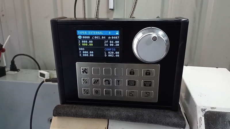
The first thing that struck us about this build was the polished, professional look of it. The enclosure for the Nucleo-64 dev board sports a nice TFT display and an IP65-rated keyboard, as well as a beefy-looking jog wheel. The spindle speed is monitored by a 600 pulses-per-revolution optical encoder, and the lathe’s leadscrew is powered by a closed-loop NEMA 24 stepper. This combination allows for the basic threading operations, but the addition of a powered cross slide opens up a ton more functionality. Internal and external tapers are a few keypresses away, as are boring and turning and radius operations, both on the right and on the left. The video below shows radius-cutting operations combined to turn a sphere.
From [Hobby Machinist]’s to-do list, it looks like filleting and grooving will be added someday, as will a G-code parser and controller to make this into a bolt-on CNC controller. Inspiration for the build is said to have come in part from [Clough42]’s electronic leadscrew project from a few years back.


Nice panel
I did a little (very short) search here on hackaday, and was a bit surprised that the gear hobbing attachment from AndysMachines had not been mentioned yet, So I’ll correct that.
He’s got a lot of gear related video’s and he’s using an encoder on his spindle and a steppermotor to keep a gear hob in sync with his workpiece and also does skiving.
https://www.youtube.com/watch?v=7WleHVtIc1c
He has also relesed the source code (asm for an atmega328)
I did not look too close at it, but I think it only does a limited number of teeth.
I especially like the last trick he added where the steppermotor can “catch up” if the main spindle accelerates too fast during power up.
I’d think an update would be to add a modified version of the Bresenham algorithm to keep everything in sync.
On the last one, he goes even far – any gear with only a slit saw – pure genius!
Yep, I’ve seen that too.
I’ve been thinking about the same, but I will only do so when I have my CNC mill fully running, including it’s 4th axis. There is no way I’m going to spend hours of time turning wheels just to make a simple gear.
And overall it’s not very practical either.
Gears are quite cheap. I can buy Gears locally (here in the Netherlands) for prices that are near the costs of the raw material 1.1730 a.k.a C45). For a price indication, have a look at tandwielen.com
But as Andy already said. It is still a viable option to make gears with big teeth on a small mill.
Came to second your mention- yes! It’s an awesome project and his documentation and videos have been phenomenal.
His project really deserves a proper hackaday article- it’s really well done.
For those who actually do need precision gears- they are absolutely not cheap. When you need ground steel gears, especially with custom keyways, it gets very expensive very quick. His cnc 4th axis gear hobber is brilliant and not a shoddy job- it’s extremely well done.
More stuff like this please! This is an amazing project.