AR Display Shows CNC Lathe Operations In Real Time

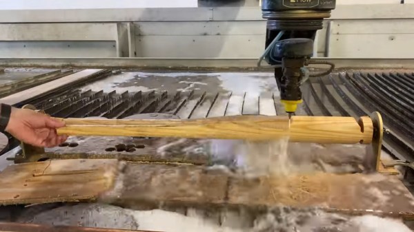
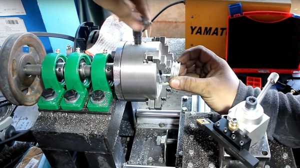
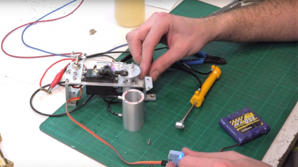
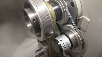
[Kent VanderVelden] has come up with an interesting AR system to assist operators who are monitoring CNC lathes. (video, embedded, below) The idea is to first produce a ‘frozen’ video stream of the workpiece. This was achieved by placing a high-speed camera above the lathe, and triggering an image capture, synchronized to the rotational position of the workpiece. A high-speed rotary encoder, attached to the tailstock via a belt drive, feeds the current position into an Altera Terasic DE-Nano FPGA eval board. This is then compared to the position from another encoder, doing duty as an angular set point control. The resulting signal is used as the camera trigger to generate a video stream of just the frames where the angle is as selected by the operator, thus giving the impression of a frozen position. The video stream is sent over to a client device based on a Raspberry Pi 4 with a UPS hat, allowing it to be portable.

High speed rotary encoder driven via a belt

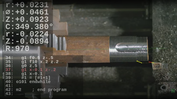
This video stream is overlaid with details of the current machine position, as well as the LinuxCNC G-code being executed and a graphical representation of the operation being performed by the machine. This combined video is then fed to a Vufine VUF-110 wearable, which is minimally invasive, allowing the operator to clearly see the machine of interest. As [Kent] suggests, there are many possible usage scenarios for such a setup, including remote monitoring of multiple operating machines by a single operator.

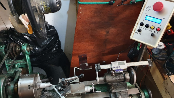
We’ve seen a few neat machine hacks over the years, here’s a nice project adding a programmable power feed to an old lathe, and since wood lathes are often missing out some DRO love, here’s a nice way to tell them that you care.

Continue reading “AR Display Shows CNC Lathe Operations In Real Time”

Electronic leadscrew

Electronic Lead Screws – Not Just For Threading Anymore

An electronic leadscrew is an increasingly popular project for small and mid-sized lathes. They do away with the need to swap gears in and out to achieve the proper ratio between spindle speed and tool carriage translation, and that makes threading a snap. But well-designed electronic leadscrews, like this one from [Hobby Machinist], offer so much more than just easy threading.

The first thing that struck us about this build was the polished, professional look of it. The enclosure for the Nucleo-64 dev board sports a nice TFT display and an IP65-rated keyboard, as well as a beefy-looking jog wheel. The spindle speed is monitored by a 600 pulses-per-revolution optical encoder, and the lathe’s leadscrew is powered by a closed-loop NEMA 24 stepper. This combination allows for the basic threading operations, but the addition of a powered cross slide opens up a ton more functionality. Internal and external tapers are a few keypresses away, as are boring and turning and radius operations, both on the right and on the left. The video below shows radius-cutting operations combined to turn a sphere.

From [Hobby Machinist]’s to-do list, it looks like filleting and grooving will be added someday, as will a G-code parser and controller to make this into a bolt-on CNC controller. Inspiration for the build is said to have come in part from [Clough42]’s electronic leadscrew project from a few years back. Continue reading “Electronic Lead Screws – Not Just For Threading Anymore”

Homemade Gear Cutting Indexer Blends Art With Engineering

Ordinarily, when we need gears, we pop open a McMaster catalog or head to the KHK website. Some of the more adventurous may even laser cut or 3D print them. But what about machining them yourself?

[Uri Tuchman] set out to do just that. Of course, cutting your own gears isn’t any fun if you didn’t also build the machine that does the cutting, right? And let’s be honest, what’s the point of making the machine in the first place if it doesn’t double as a work of art?

[Uri’s] machine, made from brass and wood, is simple in its premise. It is placed adjacent to a gear cutter, a spinning tool that cuts the correct involute profile that constitutes a gear tooth. The gear-to-be is mounted in the center, atop a hole-filled plate called the dividing plate. The dividing plate can be rotated about its center and translated along linear stages, and a pin drops into each hole on the plate as it moves to index the location of each gear tooth and lock the machine for cutting.

The most impressive part [Uri’s] machine is that it was made almost entirely with hand tools. The most advanced piece of equipment he used in the build is a lathe, and even for those operations he hand-held the cutting tool. The result is an elegant mechanism as beautiful as it is functional — one that would look at home on a workbench in the late 19th century.

[Thanks BaldPower]

Continue reading “Homemade Gear Cutting Indexer Blends Art With Engineering”

Teaching An Old Lathe New Tricks With A Programmable Power Feed

Ask anybody whose spent time standing in front of a mill or lathe and they’ll tell you that some operations can get tedious. When you need to turn down a stainless rod by 1/4″ in 0.030″ increments, you get a lot of time to reflect on why you didn’t just buy the right size stock as you crank the wheel back and forth. That’s where the lead screw comes in — most lathes have a gear-driven lead screw that can be used to actuate the z-axis ( the one which travels parallel to the axis of rotation). It’s no CNC, but this type of gearing makes life easier and it’s been around for a long time.

[Tony Goacher] took this idea a few steps further when he created the Leadscrew Buddy. He coupled a beautiful 1949 Myford lathe with an Arduino, a stepper motor, and a handful of buttons to add some really useful capabilities to the antique machine. By decoupling the lead screw from the lathe’s gearbox and actuating it via a stepper motor, he achieved a much more granular variable feed speed.

If that’s not enough, [Tony] used a rotary encoder to display the cutting tool’s position on a home-built Digital Readout (DRO). The pièce de résistance is a “goto” command. Once [Tony] sets a home position, he can command the z-axis to travel to a set point at a given speed. Not only does this make turning easier, but it makes the process more repeatable and yields a smoother finish on the part.

These features may not seem so alien to those used to working with modern CNC lathes, but to the vast majority of us garage machinists, [Tony]’s implementation is an exciting look at how we can step up our turning game. It also fits nicely within the spectrum of lathe projects we’ve seen here at Hackaday- from the ultra low-tech to the ludicrously-precise.

Continue reading “Teaching An Old Lathe New Tricks With A Programmable Power Feed”

Turning A Waterjet Cutter Into A Wood Lathe, For No Reason

On the shortlist of dream tools for most metalworkers is a waterjet cutter, a CNC tool that uses insanely high-pressure water mixed with abrasive grit to blast sheet metal into intricate shapes. On exactly nobody’s list is this attachment that turns a waterjet cutter into a lathe, and with good reason, as we’ll see.

This one comes to us by way of the Waterjet Channel, because of course there’s a channel dedicated to waterjet cutting. The idea is a riff on fixtures that allow a waterjet cutter (or a plasma cutter) to be used on tubes and other round stock. This fixture was thrown together from scrap and uses an electric drill to rotate a wood blank between centers on the bed of the waterjet, with the goal of carving a baseball bat by rotating the blank while the waterjet carves out the profile.

The first attempt, using an entirely inappropriate but easily cut blank of cedar, wasn’t great. The force of the water hitting the wood was enough to stall the drill; the remedy was to hog out as much material as possible from the blank before spinning up for the finish cut. That worked well enough to commit to an ash bat blank, which was much harder to cut but still worked well enough to make a decent bat.

Of course it makes zero sense to use a machine tool costing multiple hundreds of thousands of dollars to machine baseball bats, but it was a fun exercise. And it only shows how far we’ve come with lathes since the 18th-century frontier’s foot-powered version of the Queen of the Machine Shop.

Continue reading “Turning A Waterjet Cutter Into A Wood Lathe, For No Reason”

Assembling A Lathe From Not A Lot

Most people have a piece of equipment without which they consider their workshop or bench to be incomplete. For some, it is an oscilloscope, for others a bandsaw, but for many metalworkers, it is a lathe. Lathes are expensive if you are seeking a good one, quite cheap if you don’t mind a bad one, and sometimes even free if you can deal with a good one that’s very old and needs six burly friends and a forklift truck to move.

There is another way to acquire a lathe, and it’s one that [Sek Austria] demonstrates in the video below the break: build your own. It’s a fascinating demonstration of how machine tools evolved with each successive generation made by the last at every increasing precision. He achieves good-enough construction from a welded steel frame with little more than hand tools, and though his result is by no means a perfect lathe it does allow him to achieve the next level of machining precision. Off the shelf come a set of optical guide rails and linear bearings along with a chuck and tool holder, but the rest is all his. And the washing machine motor driving it is a touch of pure class, even though he is embarrassed enough to cover it with a glove for filming. Sometimes in our community, we adopt the sledgehammer to crack a nut methodology, using  CNC or similar techniques to fabricate things that can be made more speedily with less accomplished methods. We couldn’t help wincing at his hammering in the vice to create the lead screw nut bracket, though.

As homemade lathes go, this one is surprisingly conventional. Others have been fashioned from engine parts, or concrete.

Thanks [Xavier] for the tip.

Continue reading “Assembling A Lathe From Not A Lot”

Mini Lathe Makes Tiny Hydraulic Cylinders For RC Snow Plow

You can get pretty much any part you need online these days, but some specialty parts are a little hard to come by. So if your needs are esoteric, like tiny hydraulic cylinders for RC snow plows, you might just have to roll your own.

To be honest, we never really knew that realistic working hydraulics on such a small scale were a thing, but [tintek33]’s video below opened our eyes to a new world of miniature mechanicals. You’d think a linear actuator would be a fine stand-in for the hydraulic ram on a tiny snow plow for an RC truck, but apparently no detail is too small to address in painstaking detail. And as with many things in life, the lathe is the way to get there. Every part is scratch-built from raw brass, aluminum and steel on a mini lathe, with the exception of a few operations that were sent over to the mill that could have been done with hand tools in a pinch. The video is longish, so if you’re not into machining you can skip to 16:40 or so and pick the action up at final assembly. The finely finished cylinder is impressively powerful when hooked up to [tintek33]’s hydraulic power pack, and looks great on the plow. He’s got some other videos on his site of the RC snow plow in action that are worth a look, too.

Ready to take the plunge with a lathe but don’t know where to start? We’ve covered the basics of adopting a new lathe before.

Continue reading “Mini Lathe Makes Tiny Hydraulic Cylinders For RC Snow Plow”