We might be amidst a chip shortage, but if you enjoy reverse-engineering, there’s never a shortage of intriguing old chips to dig into – and the 2513N 5×7 character ROM is one such chip. Amidst a long thread probing a few of these (Twitter, ThreadReader link), [TubeTime] has realized that two address lines were shorted inside of the package. A Twitter dopamine-fueled quest for truth has led him to try his hand at making the chip work anyway. Trying to clear the short with an external PSU led to a bond wire popping instead, as evidenced by the ESD diode connection disappearing.
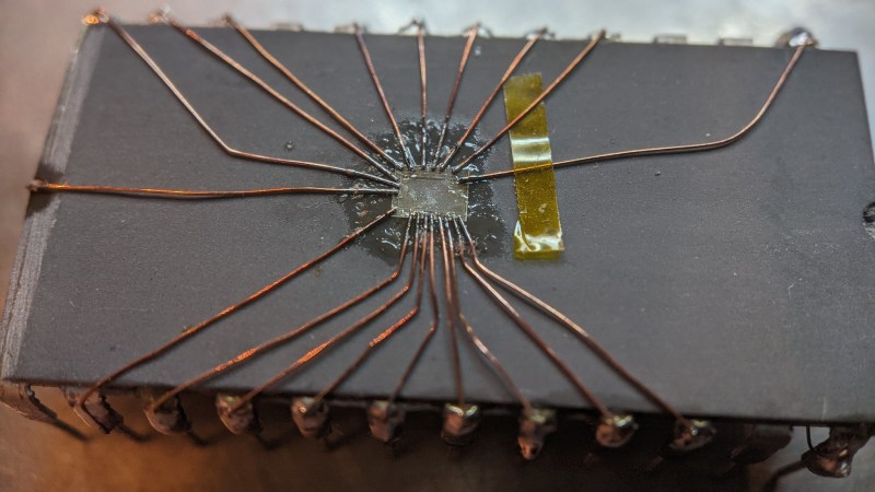
A dozen minutes of sandpaper work resulted in the bare die exposed, making quick work of the bond wires as a side effect. Apparently, having the bond pads a bit too close has resulted in a factory defect where two of the pads merged together. No wonder the PSU wouldn’t take that on! Some X-acto work later, the short was cleared. But without the bond wires, how would [TubeTime] connect to it? This is where the work pictured comes in. Soldering to the remains of the bond wires has proven to be fruitful, reviving the chip enough to continue investigating, even if, it appears, it was never functional to begin with. The thread continued on with comparing ROMs from a few different chips [TubeTime] had on hand and inferences on what could’ve happened that led to this IC going out in the wild.
Such soldering experiments are always fun to try and pull off! We rarely see soldering on such a small scale, as thankfully, it’s not always needed, but it’s a joy to witness when someone does IC or PCB microsurgery to fix factory defects that render our devices inoperable before they were even shipped. Each time that a fellow hacker dares to grind the IC epoxy layers down and save a game console or an unidentified complex board, the world gets a little brighter. And if you aren’t forced to do it for repair reasons, you can always try it in an attempt to build the smallest NES in existence!
this probably won't work but it is worth a shot. pic.twitter.com/Lv6maiEEtC
— Tube☃Time (@TubeTimeUS) January 22, 2022


There! I fixed it!
Did this person successfully repair a desperately needed, impossible to procure component – or did he just spend 27 hours of effort to “save” $1.73? Because the former would be commendable, while the latter… is the kind of math that only works if the person’s labor is only worth six cents an hour.
Could it be dumped and emulated now? Perhaps if the ROM is small enough the contents could be loaded into the RAM of a modern microcontroller. GPIO and RAM should be fast enough. If 48MHz are fast enough for USB, then old computer hardware should be as well. Either way if I’m completely wrong, enlighten me.
Last time I had to do this I used something Arduino like (probably a Mega for the number of pins) and dumped the ROM back via the serial monitor.
Then I copied the CHR ROM to some Javscript that would render it in a web page and did a screen dump / crop and your done.
https://cdn.hackaday.io/images/2066361433074078079.PNG
https://hackaday.io/project/5565/logs
Old CHR ROMS like this usually had a 5×7 pixels char in a 8×8 ROM address space and filled a 6×8 pixel screen cell.
In most of the old simple video character formats the memory wasn’t arranged as single 8 bytes long addressing for a Character as they didn’t go to video generator that way. The Video generator reads the first bite of the first chr then the first byte of the second chr … till the first byte of the last chr on the first line. Then it would move on to the second byte of each.
Often line lengths were 2^x so 16 / 32 or 64 characters. This meant the arrangement of the pixels on ROM were chosen so that vertical and horizontal scrolling could be achieved easily, even if it were done in software.
This is amazing, love the glitches before the characters start to display. Something I’ll miss about loading a tape into a C64. Today uninitialised states are too well hidden. I’ve converted fonts for espressif PROGMEM, but I’ve never seen people reverse that process and store it on different hardware.
Many thanks for linking me and explaining is such great detail!
No
This has been done; I built a special purpose reader to read out the lower case version of this chip and then programmed a 2716 UVEPROM with that data. With a wire wrapped adapter, I asded the lower case option to an ancient ADM-3A terminal with it. Sort of period correct, but of course, “not original”…
Keeping the “soul” of retro computing alive is what matters. It makes me happy when people do that.
Much like what the internet archive does for the web. People like you keep the spirit alive in modern silicon.
So you didn’t do it?
*then it should be
(give us an edit function or caffeine before we can post)
This is the kind of solder work that gives me nightmares. Seriously, are people like this shooting for the soldering Olympics or something
I had a modem got dropped back in the day and it was very expensive. I had to file the tip so small to replace a tinny resistor because I couldn’t afford to replace it (plus I had it on loan) yeah don’t drink coffee but yeah it’s great when you can fix tiny stuff that people say, oh you can’t do that without a lab and blah blah blah.
I wish there was I contest for this I’d rock, maybe lol…
I downloaded the data he put online and had a look at it.
Unfortunately it’s different to the data shown in the pictures.
Addresses 0xxx6, 0xxx7, 0xxxE and 0xxxF are empty “00000” in every cell in the data I downloaded and that’s not the case with the images in the twitter feed.
It looks like it’s interlaced data and I am very curious to find out but I don’t have an accurate dump or the chips myself.
Just in case the author drops by – and they probably already know these things –
Anything 74xx(x)00 like works together today (well mostly) so all the 5 Volts stuff like 74LS, 74HC, 74HCT, 74S but not so much 74 without the extra letters. Older chips especially DTL like these, are not as broadly compatible and DTL was Sllooowww.
So check the input and output currents and voltages and what was called fanout. To be safe use 74HCT buffers on the output pins of the old chips. Place a 100 nF cap from each power pin to ground. 74LS (or a modern 5 Volt micro-controller) is fine for outputs going to the old chip. There may be some edge cases with CMOS chips that may need 74C or 74HC (Not HCT) as buffers.
Use something like an ATmega so you can control the read timing. Keep it slow as old chips were slow and a chip that wont works at the original specified speed may still be read back at a lower speed (sometimes). Give plenty of time between setting up the chips input until you read the outputs! 1ms is fine for anything that is a static chip.
To save confusion with 74 series CMOS
74HC is a CMOS chip with CMOS voltages for I/O
74HCT is also a CMOS chip but uses TTL voltages for I/O
CMOS have higher input impedance and don’t overload the outputs of old chips but unless the old chip uses CMOS technology itself (most don’t) then you need to use HCT
I call bullshit on the soldering….