Like many people who repair stuff, [Learn Electronics Repair] has an oscilloscope. But after using it to test a motherboard crystal oscillator, he started thinking about how people who don’t own a scope might do the same kind of test. He picked up a frequency counter/crystal tester kit that was quite inexpensive — under $10. He built it, and then tried it to see how well it would work in-circuit.
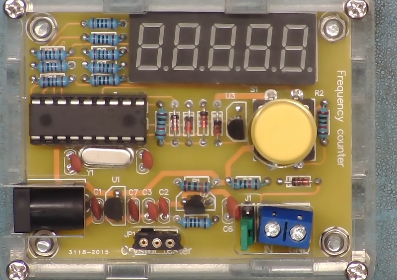
The kit has an unusual use of 7-segment displays to sort-of display words for menus. There is a socket to plug in a crystal for testing, but that won’t work for the intended application. He made a small extender to simplify connecting crystals even if they are surface mount. He eventually added a BNC socket to the counter input, but at first just wired some test leads directly in.
So how was probing with the frequency counter compared to using the scope? You would think it should work with no real problem. On the one hand, it should be easier to read the frequency from the counter, especially if you don’t have a scope that displays waveform data. On the other hand, the counter doesn’t give you any data about the quality of the clock source. Is it noisy? Clean? 50% duty cycle or 10%? Can’t tell without the scope. Turns out, though, that the cheap counter wouldn’t read high-frequency clock signals from a motherboard for some reason. It was, however, able to measure fan PWM signals.
We assume the cheap frequency counter doesn’t have a proper input stage and was loading down the crystal oscillators. The wire probe probably didn’t help any either. A proper frequency counter would probably work, but a cheap meter that had a frequency counter function didn’t do any better. He also connected a scope probe to both devices with no better results. We wondered if the 10X setting on the probe might have loaded the circuit less. We also think the preamp hack we’ve covered before might have helped.
In the end, the cheap little device didn’t seem to meet his original purpose. But for a simple crystal tester and frequency counter, it was inexpensive enough. While a proper frequency counter would probably work, scopes are getting pretty low-cost, and they can do a lot more.


I got one of these about a year ago and it’s mostly good and I haven’t played with it since. I found that it won’t work for some crystal frequencies. For me, I “think” that it was an old TV color burst crystal that failed to start the oscillator. At the time, I thought that maybe it was due to not being the right capacitive load or maybe series vs. parallel xtal issues, before I went onto something else.
In today day and age, there is simply NO EXCUSE not to own an oscilloscope.
There are option for $10 / $50 / $150 , enough to get foot in the door for any hobbyist.
Now get of my lawn and get a scope!
If you will consider modern PC can easy handle 384KHz(with some going as high as 96MHz) have 8 analog/digital input/output and smartphone with jack at least have 4 channel and with radio module can go up to 300MHz, $10 and sometime even $50 oscilloscope make no senses.
Yuck. The hard part of a scope isn’t the ADC, it’s the front end. (Generally speaking.) The front-ends of the devices you suggest are highly specialized and not suited for general test and measure use. I’d much rather have the cheap $100 import scope that is at least trying to actually be a scope.
Is this as relevant as it used to be?
Admittedly I still consider myself still starting out with learning electronics & assembling my collection of tools, but I don’t have an oscilloscope. I find myself shopping for one mostly just because that’s what one does, not because of any specific need. I still can’t think of an actual use case where I’d personally use one with the (hobbyist) work/projects I want to do – every use case I can come up with seems to be better served by other tools like a digital multimeter or logic analyser.
Playing with a scope has been a more illuminating learning experience than any number of circuit theory books. Maybe start by playing with circuit simulators and try to build something like, say, a field programmable battery array… :-) aka BMS on steroids.
Near the end of the last millennium, [Terry Weeder] published a similar 50MHz frequency counter design using a PIC16F84. If you are not familiar with it, a quick search for ‘Weeder Frequency Counter’ will provide not only the original design, but many variations. It is low cost, easy to build, works remarkably well and you probably already have most of the parts.
Actually Stan D’Souza at Microchip published an app note “Frequency Counter Using PIC16C5X” way back in 1997. Anyone else are copying that design.
Actually, Microchip did publish Stan’s AN592 (DS00592D) in 1997.
https://ww1.microchip.com/downloads/en/AppNotes/00592d.pdf
However, they also published his original AN592 (DS00592A) even earlier, in 1994.
https://www.qsl.net/om3cph/counter/anotes/an592.pdf
Applications for his use of the 8-bit prescaler in frequency counters was soon ubiquitous. One of the earliest implementations was done as a class project under Luigi Rizzo, former associate professor at the Dipartimento di Ingegneria dell’Informazione of the Università di Pisa, Italy. http://www.iet.unipi.it/~a007834/
The course project by Simone Benvenuti and Andrea Geniola used four 7-segment LED’s to display the frequency in an exponential format.
Both the source code and schematics for their project can be found at:
http://www.iet.unipi.it/~a007834/pic.html
Enough with the history.
Unusual to display menus on 7seg displays? Where have you been hiding since the ’70s?
Cheap frequency counter modules come in two forms. The ones with LCDs and the ones with LEDs. The latter seems to be the domain of the crystal testers, and fancier ones that can be programmed with an offset for use with a receiver.
There’s nothing functional about it, either could use LCD or LED readouts.
This article about calibrating crystals leads down a learning path about frequency standards and how accuracy can be calibrated and handed down to less accurate oscillators. Ultimately, what accurate standard does your measuring tool compare against, and how stable is your device over time and frequency? Then you know the limits you approach as you attempt to calibrate other oscillators with it. SImple example… Calibrate the XO in your clock radio. How well you achieve this is a major factor into how accurate your clock is over time. How many seconds per month, or per year your clock remains true. Good luck!
How quickly we forget. A shortwave receiver with BFO and small loop probe will allow you to check oscillator circuits without loading them.
Noob question: I can see how you could use an oscilloscope to eyeball whether the clock signal has noise, but can an oscilloscope be used to quantify the noise?
On scope with a good timebase and precision trigger, you can measure the clock jitter. i.e. variations in clock periods over time. You’ll need both because you are comparing the scope’s frequency reference to your clock at a precise voltage level. Junk scopes limits what you can measure.
https://www.tek.com/en/solutions/application/jitter-measurement-and-timing-analysis
Ah, I see. Thanks for explaining 😀
Hey it seems I’m famous LOL! I made this video because a lot of my channel subscribers live in countries where local economic conditions make it impossible to own something like an oscilloscope. Bu there is also good money to be made locally by repairing old items that would be thrown away elsewhere.
Although the project was not a total success, I’m keen to modify this if it can be made to work, and publish a part 2 of this video – so all suggestions are much appreciated. Richard.