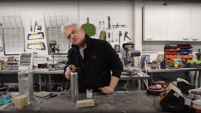
[Robert Murray-Smith] presents for us an interesting electronic device from years gone by, before the advent of Silicon semiconductors, the humble metal oxide rectifier. After the electronic dust had settled following the brutal AC/DC current wars of the late 19th century — involving Edison, Tesla and Westinghouse to name a few of the ringleaders — AC was the eventual winner. But there was a problem. It’s straightforward to step down the high voltage AC from the distribution network to a more manageable level with a transformer, and feed that straight into devices which can consume alternating current such as light bulbs and electrical heaters. But other devices really want DC, and to get that, you need a rectifier.
It turns out, that even in those early days, we had semiconductor devices which could perform this operation,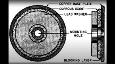 based not upon silicon or germanium, but copper. Copper (I) Oxide is a naturally occurring P-type semiconductor, which can be easily constructed by heating a copper sheet in a flame, and scraping off the outer layer of Copper (II) Oxide leaving the active layer below. Simply making contact to a piece of steel is sufficient to complete the device.
Obviously a practical rectifier is a bit harder to make, with a degree of control required, but you get the idea. A CuO metal rectifier can rectify as well as operate as a thermopile, and even as a solar cell, it’s just been forgotten about once we got all excited about silicon.
Other similar metallic rectifiers also saw some action, such 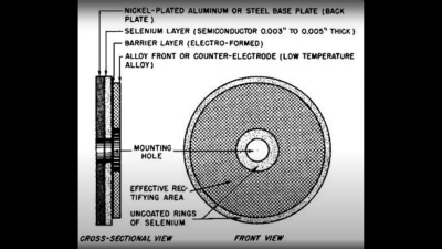 as the Selenium rectifier, based on the properties of a Cadmium Selenide – Selenium interface, which forms an NP junction, albeit one that can’t handle as much power as good old copper. One final device, which was a bit of an improvement upon the original CuO rectifiers, was based upon a stack of Copper Sulphide/Magnesium metal plates, but they came along too late. Once we discovered the wonders of germanium and silicon, it was consigned to the history books before it really saw wide adoption.
We’ve covered CuO rectifiers before, but the Copper Sulphide/Magnesium rectifier is new to us. And if you’re interested in yet more ways to steer electrons in one direction, checkout our coverage of the history of the diode.
Thanks [Setvir] for the tip!


There were copper diodes into the transistor age. I remember an article where someone took a razor charger apart, and there was a copper diode of some sort. Very small.
Some budget HiFi systems in the 70’s used copper semiconductors too.
Can you cite a reference? I have never heard of any commercial semiconductors based on copper once germanium and then silicon became available. I do recall an old model train “transformer” I had about in 1962 that had a selenium rectifier, which were common then, but now it’s known to be a hazardous element.
Selenium isn’t very toxic, and in fact you can suffer from Selenium deficiency. ie you need _some_ but not very much. (I admit I didn’t know this until I looked at the Wikipedia page which I looked at to confirm my feeling that it wasn’t _very_ dangerous. )
Sure, trace amounts are necessary for life, but like iron, too much can kill. See: https://e360.yale.edu/features/from-canadian-coal-mines-toxic-pollution-that-knows-no-borders
there were (may still be there) monitoring wells in a town near me as a result of selenium (used to coat photocopier drums IIRC) it is indeed toxic as most things are to one extent or another in the wrong form or concentration..
I’ve worked on equipment into at least the 1950s with disc rectifiers. A Western Union Telefax machine come to mind – though that was selenium and I believe there was also a 5Y3 for tube plate voltage.
I also have a 1932 Teletype Model 19 with a saturable core transformer in the DC supplyfor voltage regulation. There are huge disc rectifiers which I suspect are copper oxide. The Teletype regulates by using only the output voltage fed back DC to a third winding on the transformer. As DC output voltage increases, the core is more saturated and mutual coupling is blocked and thus decreases output voltage. Pretty clever.
Selenium rectifiers were practically “consumable”…and they had large fins because selenium does not like heat at all. Radio restorers usually leave them in place to keep the appearance period correct and hide a silicon diode somewhere that actually does the work. When selenium rectifiers fail, they supposedly smell awful.
The saturatable transformers worked by introducing a dc field into a smaller leg of the transformer. The core at that point would saturate and block AC fields. A small dc field chip is then control a much larger ac field. The technique was called the magnetic amplifier. A couple of down sides was linearity an frequency response. The former was limited by the core BH curve and the latter by the core losses at higher frequencies. Silicon steel could is get you to around 300Hz control frequency response. Heavy duty, indestructible amplifiers of the 1950s.
I’m absolutely sure that it wasn’t a diode actually made of copper (oxide), it was just copper colored, which is quite common for glass enclosed diodes, like this one:
https://www.engineersgarage.com/wp-content/uploads/2021/07/TCH27-04-DO-35-zener-diode.png The color of copper oxides can be green, red, black, and in-between, depending on which compound(s) is(are) present.
I can’t not put a link to this text from the days where “thermionic valves”/”vacuum tubes” were the bleeding edge:
http://www.tubebooks.org/books/erav.pdf
I happened upon a physical copy in a library discard pile… so surreal to read about some of the “rectifier” tech that preceded both tubes and the above devices. The mercury arc rectifiers in particular…
N
At least Ivo Shandor was able to make good use of them
Gotta make those girders somehow.
I had a 1960-vintage VOM (Volt-Ohm-Milliammeter, for you young-uns) that had a copper oxide bridge rectifier for its AC ranges. As I recall, its forward voltage drop was pretty low; lower than germanium diodes.
If you want to challenge your hacker friends some time, ask them how many different devices have been used as rectifiers. If they know their history, there are over a dozen! Silicon and germanium are only two…
Aside from vacuum diodes, gas-filled rectifiers that used mercury vapors (great for high voltage and high current applications) I know of selenium rectifiers, copper ones, galena crystals used for crystal radios, pencil and razor blade one I found in a book of experiments for kids, and my favorite idea: an AC motor coupled to a DC generator. This system with multiple generators generating variety of voltages at kW and MW power ranges was used in 1950s and 1960s to power polish state radio stations. In early days of radio a purpose-built alternator generated HF AC voltage for use as a carrier…
gas flame is still used to rectify a sensing current in some spark ignition devices (furnace etc,) And don’t forget silicon carbide crystals for radios (similar to galena cats wisker I was told
Here’s one that kinda got left behind: Permag-Bias Relay Rectifier (see Hand Tool Rescue’s Restoration of a car battery charger from That Era). as the descriptive-name suggests (I don’t know if it even has a formal title), it uses a fairly conventional coil relay with a small permanent magnet on the armature to give it a (probably very nasty and noisy) half-wave rect
My lathe had several selenium rectifiers, including a fairly powerfull three-phase bridge.
I kept them, but replaced with silicon, freeing up enough space to fit a few billion transistors (ie, a PC and motion control cards)
My understanding is that Selenium rectifiers make a very foul smell when they blow, making diagnosis easy.
If anyone is interested, before and aftee shots of the rectitiers:
https://photos.app.goo.gl/cTrnEnkvvmfrkTya6
https://photos.app.goo.gl/LXqutQFhwur8Y4Jh6
even without MOS-Diodes, there were still ways to rectify AC to DC, such as Magnetic Oscillating Rectifiers. Hand Tool Rescue has a really interesting video on restoring a car battery charger made with that method. The working principle is a solenoid relay with a biasing permanent magnet on the armature
AKA vibrator, back when it had a different meaning.
Vibrators were used to go the other way. Turn DC into AC. I once had a car radio that used one.
They came in two types. The asynchronous type used a rectifier at the output of the transformer, the synchronous type used a second set of contacts on the vibrator to rectify the output.
To go AC to DC it was quite common to use a motor-generator with a AC motor and DC generator/dynamo. Since the efficiency of both was rather sucktastic in the past, I’d guess you’d maybe get 20-30% overall efficiency.
The efficiency wasn’t that bad. Take this scenario – You have a telephone exchange where up to 10,000 people may be hearing ring tone sound (not ring current that rings the bell).
Now imagine that as a Class AB amplifier, How low the output impedance would need to be and how much energy is wasted as heat.
Compare that to a motor driven sound generator that has a complex secondary winding (generator output) to make the specific frequencies of the sound.
A vibrator was a way to get high Voltage in a car to run the radio’s vacuum tubes. The original ones used heating elements to toggle the DC into a transformer to kick up the voltage as a sloppy AC, but it got the job done. The contacts would wear out like those of a relay, which could itself be toggled to get the job done. See: https://www.vintagecarradio.com/blog/radio-vibrators/
Later, germanium transistors were used as the active element in vibrators for vacuum tube radios (some, like police radios, still used them). I bought an RCA transistor manual in 1964, and they had example circuits for vibrators (and 12V car amps) in the back It’s the origin of the term multivibrator before being supplanted by oscillator. See: https://en.wikipedia.org/wiki/Multivibrator
There was the synchronous motor turning a shaft with an adjustable disk. Brushes are connected in such a way as to got the same output you would get from a modern bridge rectifier but without the voltage drops. I rarely see it today, but this was the way top get high voltage DC. You can do this with the output of a neon sign transformer or any source that uses the mains. Synchronous rectification. For high voltage you don’t need brushes, just use a small gap. I can’t find a combination of search terms that will dig one out of the static on the Internet.
Using clock face references here, construct the rotor disk from plexiglass/perspex, and place two conductors, one from 12 to 3, the other from 6 to 9 on it. Now arrange an adjustable but otherwise stationary ring around the edge of the rotor, and rig gaps to feed your HV AC at 12 and 6, and take DC off at 3 and 9. Spin the rotor at 1800 RPM synchronous. Depending on the fixed angle between your rotor and the synchronous drive motor’s poles, the optimal position of the stator ring will need to be found. (Alt. you could make the ring absolutely fixed, and tweak by remounting the rotor disk to the motor shaft)
No one mentioned the high voltage mercury rectifier? Is still around a century ago or a bit less… :D
https://en.wikipedia.org/wiki/Mercury-arc_valve
I think language is playing a role here.
Today (for most people) a diode is a diode.
Before power rectifiers were rectifier (diodes) and AM receiver detectors were detector (diodes) but the “diode” part wasn’t often mentioned as the first part describes it more accurately.
Today, to be more accurate there are Small Signal Diodes and Power Diodes and plethora more diodes.
There isn’t a mention of old AM receiver detector diodes and that’s a bit of a shame. As they say constraints can create ingenuity and that is very very true if you look at what WWII prisoners of war used to create AM detector diodes so they could at least hear from the other side. Some radio programs realised that POW’s had receivers and deliberately encoded secret messages into programs by the choice of words and / or simple cryptology.
There are a couple of other archaic rectifier technologies. There’s the rotary converter which uses a commutator driven by a synchronous motor to flip half cycles of the AC input to the same polarity by mechanical switching.
I have also run across an article in a 1920s issue of Popular Mechanics on Google Books – Build a liquid rectifier – for recharging LeClanche cells. I have found rectifier jars for sale on auction sites.
As a kid my buddy and I made a carbon rod arc furnace from a book. It had a glass dish with baking soda and a lead fishing weight. I believe it acted as a crude rectifier. The gallon of water would boil in like 20 secs. Fun times
Long ago the Earth was young and I was a sailor. I remember well the distinctive aroma of a failed selenium rectifier. Also saw some mercury vapor rectifiers.
I knew a guy who was a ham radio operator in the 1930’s. He said diodes only cost a dollar, but nobody had a dollar, so he made his own via this technique.