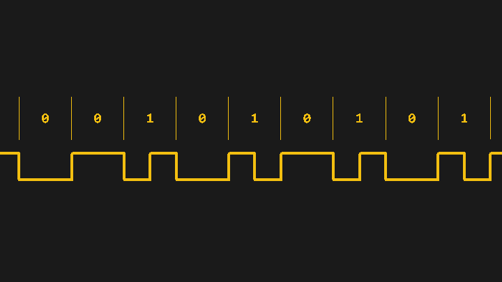
We often take our “SoftwareSerial” libraries for granted, and don’t investigate what goes on under the hood — until they fail us, at least. Would you like to learn how to harness the power of interrupt-driven bitbanging? [Jim Mack] teaches us how to make our protocol implementations fly using the LTC protocol as a springboard.
LTC (Linear/[Longitudinal] TimeCode) is a widely-used and beautifully-crafted protocol that tends to fly under our radar, and is one that hackers could learn plenty from. It’s used for synchronization of audio/video devices during media production and playback. LTC’s signal is almost digital but not quite: it doesn’t need a clock, and it has no polarity. Additionally, it mimics an audio signal really well, you can decode it at any playback speed, and many other benefits and quirks that [Jim] outlines. You do need to maintain the timings, though, and [Jim]’s article shows us how to keep them right while not inconveniencing your primary tasks.
Using interrupts means that your main loop gets to do other things, effectively letting you run different kinds of tasks in the background. [Jim] implements an LTC protocol transmitter using interrupts fired off at a defined frequency, doing LTC data processing in the main loop, and the time-critical GPIO wiggling from inside the interrupt handler code. He explains the code structure and the nuances along the way, and in the end, even provides us with source code of a highly capable and configurable LTC transmitter project for us to study and reuse. Be it RF transmitter bitbanging, IR remote signal reception, UART emulation, or any other protocols your MCU lacks peripherals for, this is where you learn to get it working.
In [Jim]’s previous article, he’s gone to great lengths explaining the fundamentals of precision and accuracy, then putting these theories into practice again, using an ATMega. In the next write-up of this series, he would like to create an LTC decoder, teaching us even more about properly using interrupts for timing-sensitive tasks. We can’t wait!


LTC is not trivial to implement fully, especially when reading it at different speeds and using it to sync tape transports or other hardware. 20+ years ago, the few systems capable of syncing tape machines cost thousands. This article is great; I’m really looking forward to seeing the followup on reading LTC.
I believe the same protocol is used for S/PDIF and AES/EBU.
S/PDIF and AES/EBU use manchester encoding, with a bit of “weirdness” added to synchronize on frames, and manchester always has a transition in the center of a bit.
I’ve also done ISR based serial decoding and the main limits are ISR latency and the speed at which you can handle ISR’s. My application was for catching DCF-77 signals, so with a pulse only once a second it was quite easy on the microcontroller. I already had a clock-tick timer ISR (at either 100Hz or 1kHz, can’t remember) so measuring the pulse with in the ISR was just comparing two numbers. For me, this method had two benefits. Because it fully runs in ISR’s, all code is local there, so it does not complicate the flow of the main program. Also, by measuring the actual pulse widths generated by the DCF-77 radio you can make an estimate of the signal quality.
>LTC’s signal is almost digital but not quite: it doesn’t need a clock, and it has no polarity.
What? How does that make it not digital? Not needing a clock just means it’s asynchronous (like UART), and being polarity insensitive (differential encoding) is a fairly common requirement for line codes.
In fact, from your description and timing diagram, LTC is encoded using ‘Differential Manchester’, a fairly common digital line code.
As the cited article says, it’s actually bi-phase mark encoded, similar to Manchester. It is a digital signal, just adapted for analog transmission and recording. It does require a clock, but not a separate one — it’s self-clocking.
Bi-phase mark encoded is just another name for Manchester. There’s no difference.
>It does require a clock, but not a separate one — it’s self-clocking.
Yes, that’s how just about every asynchronous line code works.
Manchester coding is also called biphase level coding. Biphase mark coding is one form of Differential Manchester. As you say, all such codes share some characteristics.
“it doesn’t need a clock, and it has no polarity.”
That hurts. Should read: “it is self-clocking and DC-free”
I might plan to reverse engineer the one out of a Sinclair Interface 1 expansion ROM, since that can get 19,200 out of a 3.5ish Mhz Z80
A word of warning: every time you do something with interrupts in an Arduino, remember that Arduino “secretly” uses an interrupt to service the millisecond counter and to push bytes into the serial buffer – so you will either mess up Arduino’s internal timekeeping, break delay and serial functions, or Arduino may mess up your ISR timing.
Either you accept that your servo, stepper, etc. routines will be jittery, or you disable the other interrupts and risk causing weird bugs with almost everything you do with various Arduino libraries.