There are many ways to make a linear actuator, a device for moving something is a straight line. Most of the easier to make ones use a conventional motor and a mechanical linkage such as a rack and pinion or a lead screw, but [Ben Wang] has gone for something far more elegant. His linear actuator uses a linear motor, a linear array of coils for the motor phases, working against a line of magnets. Even better than that, he’s managed to make the whole motor out of a single PCB. And it’s fast!
This represents something of an engineering challenge, because achieving the required magnetic field from the relatively few turns possible on a PCB is no easy task. He’s done it by using a four-layer board to gather enough turns for the required magnetic field, and a simple view of the board doesn’t quite convey what lies beneath.
PCB motors are perhaps one of those areas where the state of the art is still evolving, and the exciting part is that their limits are being pushed right there in our community. And this isn’t the only linear motor we’ve seen recently either, here’s one used in a model train.


It seems neat, but I’m very confused about where the magnets are and why the steel plates are so huge.
The CAD drawing sucks and doesn’t show any magnets, and the image is so small that you can’t see any details.
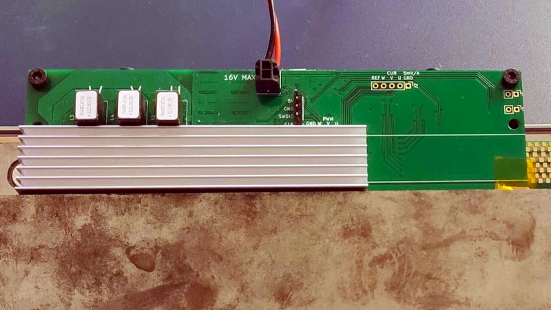
Are the magnets the gold and green checkboard shown in the image? it looks like an additional PCB. ???
He clearly did, as that is where the CAD image is visible. The link blog entry does not show the magnets in any photos, nor the CAD image indicate where they are positioned.
“The motor is constructed with two mild steel plates, sandwiching an aluminium spacer. Parts were made at SendCutSend, which was quite fast and reasonably priced. The magnets (not shown in CAD) are simply just placed on the steel plates. No additional attachment required. Assembly is quite tricky due to the strength of the magnet, but can be done with some non-magnetic spacers (I used scrap FR4 PCBs).
The linear rail is mounted to the bottom plate with a 20mm x 20mm aluminium extrusion. The motor PCB is attached to the rail blocks with a 3d printed mounting block.”
looking at the image given above that paragraph you can quite easily guess 1) where the magnets are and that they’re not the gold and green checkboard.
I aggree such a pic needs annotations, though!
“50mm * 10mm * 2mm magnets were used (which are a bit smaller in reality by ~0.5mm in each dimension), as they were easily available on EBay etc.”
So they are clearly not the gold and green checkerboard. I wonder what that PCB is for, maybe he uses it for an optical encoder?
given the price of pcb’s these days, it almost seems cheaper to turn it inside out. twice the pulling force and only a few magnets needed. you could probably cut an inductive encoder right into that pcb and untether the carriage all together.
I hear a lot of noise when this thing moves back and forth. What are you using for bearings?
I’ve worked in the past with high quality high precision linear motors, using top grade ball bearings, and they do indeed make quite a racket when they go fast. I’d wear hearing protection if I had to spend the day in the same room
In my experience it depends on preload. If you want precision and bidirectional load capacity (important if you’re putting any moment through the group of cars), you really want cars with relatively high preload. Higher preload tends to be noisier, I think because you’re actively pushing the balls/rollers hard into the raceway at high speed, effectively a continuous series of controlled metal-on-metal collisions.
I’m impressed. I like how [Ben] used the Finite Element Method Magnetics (FEMM) application to simulate the design.[1] The FEMM simulation files are contained in [Ben]’s kingoflolz/linear-actuator-hardware GitHub repository.[2] FEMM runs natively in Windows but it will run in Linux under Wine.[3][4] FEMM is free and copyrighted. While at first glance FEMM’s license looks innocuous, it is rather complex. To examine the license download the source code [3] (builds with Visual Studio 2008 and Visual Studio 2017), unzip the downloaded archive, and read the license.txt file.
* References:
1. FEMM (Finite Element Method Magnetics) simulator:
https://www.femm.info/wiki/HomePage
2. kingoflolz/linear-actuator-hardware/simulator/
https://github.com/kingoflolz/linear-actuator-hardware/tree/master/simulator
3. FEMM for Windows (binaries and source):
https://www.femm.info/wiki/Download
It might be worth giving these tools a try as well:
http://www.agros2d.org/features/
https://freefem.org/
Though I’m a user of FEMM myself and haven’t done as much with the others (which are in part more powerful). The FEMM UI is a bit dodgy, but you can import your geometry as dxf and complete the problem setup from there.
That was REALLY helpful. I’ve been searching for a simple to use fem package for electrostatics for rather long and didn’t ever turn up anything useful out of the box (without spending a month learning how to use it). BIG THANKS!
Neat. I wonder if dropping all magnets and replacing there with a similar PCB would allow for more precise and/or fast control.
Quality professional grade project from an Undergrad. Refreshing change from meh-arduino stuff. HaD seems to be surfacing some less mainstream stuff of late, hoorah.
What a great project!
This is really awesome. From my understanding, he didn’t use rare earth magnets. There are many applications for this, such as laser scanning for a light laser module. Lighter, smaller, greater precision and lower costs linear actuators.
I would like to know what is the maximum torque this can achieve. I’m assuming he is using a heavy steel plate to prevent any wobbling since electromagnetic linear actuators can really accelerate super fast and then instantly stop and move the opposite direction, all in a fraction of a second.
So what we’re all really wondering, as it is mentioend neither in the blog post nor this hackaday article, is how much force it can provide. How many N or milliN?
From the graph on the blog post, 12 N (2.7 lbf) at 20 amps. That’s a lot of current and I imagine it would be a problem in an environment requiring low eletrical noise.
Truly impressive. I hope it’s possible to 3d print this (and PCBs in general) in the future to allow for some truly fancy projects.