Perhaps nothing added quite so much to the charm of vacuum tube circuits from back in the heyday of the vacuum tube as did the “Magic Eye” indicating tube. With the ghostly green glow of its circular face, magic eyes stood in for more expensive moving-coil meters for things like tuning indicators and VU meters. And while they may be getting hard to come by today, fear not — this solid-state replacement for the magic eye tube is ready to stand in for your restoration projects.
To pull off this clever build, [Gord Rabjohn] started with original 6E5 and 6U5 magic eye tubes, presumably ones that either no longer worked or had become too weak to see. The glass envelopes of the cathode-ray tubes were carefully cut from the sockets, and the guts of the tubes were discarded to make room for the replacement circuit, which lives on two PCBs. A rectangular control board holds an LM3915 bar graph LED driver chip, while a round display PCB holds 120 surface-mount green LEDs. The circular display board is mounted at the top of the control board and perpendicular to it, with a diffuser mounted above the LEDs. Everything is stuffed back into the original glass envelope and socket, making this a plug-in replacement for the tube.
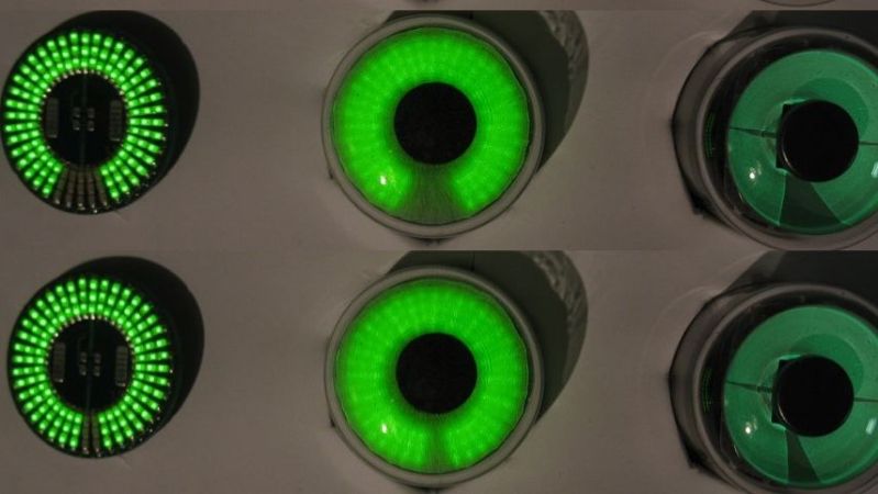
The effect is quite convincing, as shown in the video below. True, you can see some evidence of the individual LEDs even with the diffuser, but honestly this just makes the display look more like the iris of an eye. We really like the look of this and we appreciate the work [Gord] put into it, especially the documentation. For a little more on how the tubes worked, check out [Al Williams]’ article.
Thanks to [Adrian] for the tip.


Excellent!
Now to build replacement LED displays for early HP calculators…
Yes, its actually pretty cool!
And its ironic that a magic eye would have been cheaper than a meter.
I’m not sure when the transition point was, but early meters were insensitive, and I think fragile. Early volt ohmmeters were 1K per volt, while fifty years ago it was easy to get 30,000 ohms per volt.
A magic eye tube wasn’t just an indicator, there was amplification built in. It gave you a relative strength meter, maybe more for show than need.
I suspect that eye tubes continued through habit, I once had a taoe recorder from the sixties with an eye tube.
Communication receivers went to meters about WWII, or maybe earlier, but much more expensive.
In the sixties there were lots of cheap meters, so they went into a lit, forshiwing relative voltage or strength. None were really calibrated. But in the seventies, the local surplus place had loads, small, only a relative scale.
A faceted diffuser might make it look more sharp and prevent hotspots at the same time.
I already thought of making one using pov. It would be a bulkhead with a cut and an LED behind it turning on and off.
That could probably do a really good job. I don’t like the diffuser on the one in the article, since the edges on real eye tubes were quite sharp. I’d almost rather see it used without the diffuser, since it’s nowhere near convincing anyway.
Follow up thought; although more difficult to build, each trio of LEDs could have their own diffuser, giving a sharper transition between levels. That would not be as fine of resolution as the original vacuum tube, but…
+1
Agreed! I was thinking “how can we get the constant (not-stepped) behavior of the old deflection screen?” and started wondering about tracing with either galvos but POV is 1000x easier. Since its a tube there is obviously tons of extra power for spinning a disk.
The hardest part is always the slip ring… wish there was an easy and reliable way to replace it.
Tracing with point of view? What does that mean?
https://create.arduino.cc/projecthub/theSTEMpedia/persistence-of-vision-pov-display-using-arduino-583d5f
Slightly more complicated but you might consider using modulated AC over an air gapped transformer to transmit both data and power. A coil on the tube body that matches up with a coil on the PoV PCB, using a simple one way protocol that just gives the PoV PCB the scale would be fine.
You could just spin a continuously-illuminated green bar and turn it off for the desired, variable slice of pie out of the circle.
Go full retro and spin a slit disk with a single LED backlighting it ala nipkow
I came from the future to explain better… The LED would be static, along with the electronics to blink it. Only the disc with a small cut would be rotating, so you could blink the led and get the radial shape you wanted. No rings hurt in the process.
Nicely done, looks pretty good.
I wonder if a round LCD or OLED display would be more granular. They would probably need an MCU to drive them. Something like https://www.good-display.com/product/0.75-inch-round-small-white-128×128-dots-OLED-display-GDOR0075W-288.html
Round LCD – THIS!
https://www.buizenradioclub.nl/forum/34-repro-onderdelen/25170-am1-em1-vervanger
In Dutch but people are already working on that
My first thought too. Maybe this one: https://youtu.be/eJBDXjI5Zu4?t=170
I figured it would be a smartwatch display run by a microcontroller…. but this is simpler.
Now it just needs the ‘best diffuser from Amazon’ video to fix that diffusion
Crazy how simple that circuit is…and it still works as a drop-in replacement for an original!
That chip is so old, there’s not even a SMD version of it. Guess it will be obsolete in a few years, too? But there seems to be a good variety of modern alternative LED drivers, maybe not exactly as simple to interface, though.
“there’s not even a SMD version of it.”
It’s not a bug, it’s a feature.
SMD isn’t clever, at all, I think. There’s no mechanical support, at all. Very unprofessional! If something heats up, it will fall from PCB. Or, even worse, will glide across the PCB and smear solder all over it. Veeery clever. Not!
Through-hole all the way. 😎👍
Each has their place. I wouldn’t want a smartphone built out of only through hole components nor would I want something high powered that has to operate in a high temp/vibration environment build out of only smd. Also pretty silly to worry about rohs leadfree desoldering itself during operation when long before that point you’d have much bigger problems whether pth or smd. By the time things got that hot for long enough no matter how the chips are mounted there’d be permanent damage to the parts and/or the pcb.
Nice build ! However not all magic eyes were green but neon orange (didn’t see this in the article). My grandmother’s Revere T100 tape recorder had an orange bulb one that would flicker according to microphone volume. The neon bulb had 2 tiny fingernail shaped electrodes that the neon plasma would dance around. You can find this recorder on eBay and the magic eye is at the top between the two reels.
That’s technically not a magic eye, which is a cathode ray tube of sorts. The orange bulb is cold discharge neon bulb. Same technology as a Nixie tube.
portal turrets.
just go red.
MAX7219 BarGraph Example Sketch
https://github.com/csdexter/MAX7219/blob/master/examples/MAX7219_BarGraph/MAX7219_BarGraph.ino
I’ve seen a few of these LED magiceye replacements but this one has the most LED. I honestly think a oled display would be easier in the end.
Tapering the rings of LEDs would have made it feel more like the original. When the real tube fills up, the outer edge is slower than the inner edge.
This project caught my eye just as I was agonizing over the ethics and morality of “solid stating” thermatrons: https://soldersmoke.blogspot.com/2022/08/building-solid-state-magic-eye-and.html
Major cool ! ! !
Very nice indeed.
A smd uC with enough digital i/o pins, one analog input and some code can easily replace the lm3915, so that is not a problem; however it still uses a relatively small number of leds, therefore the granularity offered is less than ideal (just like the lm3915). A solution could be employing one of those very small oled displays which hopefully should offer enough resolution to implement the same function with added precision and without noticing the led rows. As an added bonus, it could implement different kinds of magic eyes one could switch just by changing the state of one or pins, or setting a predefined voltage on a second analog i/o.