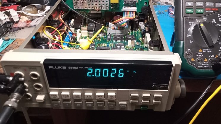
[William Dudley] picked up a Fluke 8840A bench multimeter at an auction, but was sad to find out that it was reading resistances inaccurately. It was also missing the optional board to enable AC measurements. Desiring to use the otherwise lovely meter, he set about repairing and upgrading the device.
Thankfully, the 8840A was from a time when Fluke used to openly publish schematics in its manuals. Thus, combined with taking a look at some photos online, it was straightforward for [William] to recreate the original AC “Option 09” board to enable the desired functionality. As is usually the way, his efforts didn’t work first time, but after some bodge wires were installed, all was well. [William] reports the measurements are “reasonable, maybe even sufficient” with no calibration undertaken.
Repairing the resistance issue was easy. It turned out to be corrosion on the selector switches, revealed when high-resistance measurements were accurate, but low-resistance measurements weren’t. A bit of flick-flacker with some contact cleaner sprayed into the switches got things working again nicely.
It’s nice to see old hardware restored to full functionality, particularly when it’s as attractive and well-built as an old Fluke meter. Bringing back old tools from the dead? You know we wanna hear about it!


I have mixed feelings about this.
Yes, he got something that was broke and “fixed” it. But a Fluke is held to a high standard (no pun intended? ) and this one falls short. Sort of like a Toyota Corolla that gets lousy gas mileage and keeps breaking down.
Anybody who uses “old” test gear, be it scopes, voltmeters, frequency counters, has to deal with the question of calibration. Most of us aren’t fortunate enough or rich enough to own a “real” calibrator, or rich enouth to pay a service to calibrate them. So we do what we can. My Fluke, despite being “out of calibration”, is still the best meter on my bench, and plenty good enough for hobby electronics use.
Honestly, it’s better than any voltmeter I used in my long career as an engineer. As to “keeps breaking down”, I’ll stake my two electrical engineering degrees that this Fluke lasts long enough to be inherited by my son.
I think this is awesome… Despite being obsolete these are still fine meters – and they’re a bargain for hobbyists. I’m glad to see this get fixed, updated, and continue to be used. Nice job William, and great writeup!
Bill, some people don’t appreciate a job well done. I’m keeping your files handy in case I need to upgrade one of those Flukes. I have one now with the AC, but may get another one to fix and add on. Who knows.
Bill, I owe you a debt.
About 2 years before you published this I also created a homebrew version of the AC-09 based on the 8840 Fluke schematics. Mine worked ‘okayish’ but were never reliable. After reading your blog and deciding to give it another go, I dragged my boards out and spent a weekend troubleshooting. The ver2 boards now work perfectly and are nicely calibrated to my other more modern meters.
You’re right about the 8840 and 8842 being solid meters. They will outlast anything and, one calibrated, are easily in the same class as modern 5.5 digit meters.
For anyone else building one of these the relays caught me out and I had to bodge them. Stick with the reed relays and don’t try to substitute for armature based relays.
One of my 8840A’s has a plastic shield on the AC adapter board. Is this somebody’s bodge or was this an alternative from Fluke ?
I am building the DIY AC adapter I was thinking of copper for the shield but could I use conductive PLA for the shield ??
Dave
Hi William,
I purchased two of your boards and haven’t finished putting them together. Do you know where I can obtain the AD611KQ IC’s?
Thanks
David
It would be nice if someone with a 3D printer could come up with the shields for these boards. Unfortunately, I don’t own a 3D printer.
I have just finished an AC option board of my own based on the above. I had great problems getting 0.1% precision wire ended restistors so ended up respining the card to use 0.1% SMD devices and using multiple in series to make the “odd” values needed. I got around the need for a 1.1pf cap by using two 2.2pf in series. I could have converted all the R’s and C’s to SMD but thought that may be tempting providence!! The shield I fabricated with spare plain PCB board, soldering the edges togeather. The result seems to work almost as well as the real thing, though I dont know how well it would stand up to a formal calibration. Now, if only there were a DIY HPIB (IEEE) card … I can dream …
Dave
I’m looking for the files and other info in order to make my own “09” board.
Does anyone know where to find them?
Kind regards,
Cees van der Leeuw
The Netherlands
Did you try visiting the web site linked to in the article and downloading all the files from there?