Solar garden lights and many other similar trinkets typically rely on cheap rechargeable batteries as a power source when the sun isn’t shining. [Darryl] figured that a supercapacitor could do the job instead, and set about building a solar supercap power supply that could run various projects.
The power supply is built to use a small 60 x 40mm solar panel that provides approximately 500 mW at max output. This charges two supercapacitors which feed their output into a TPS61200 boost converter, specifically designed for working with ultra-low input voltages down to 0.3 V. The boost convert can then be configured to output 3.3 V or 5 V depending on the desired voltage for the device to be powered. A special MOSFET array part is used to charge the dual supercaps in series, ensuring they stay balanced and don’t get overcharged by the sun.
The design has worked well in practice. [Darryl] reports that it has successfully powered a LoRa device reporting every 10 minutes for over two years without issue.
Solar power is a magical thing, capable of providing energy for free if you can get out there and capture it. If you’re working on your own solar-powered projects, don’t hesitate to drop us a line!


This project may be just what I am looking for to get my remote weather station working again!
Holy crap, I had the same idea a few weeks ago—and also thinking of converting my 18650 solar weather station to supercaps.
Love it.
I did something a little different. Wish I could attach a picture. I used a single TP0604 P-Channel enhancement mode MOSFET and a diode to run my solar powered light. Connect the diode Anode to Source and Cathode to Drain of the MOSFET. Connect the positive output of the solar panel to the Source of the MOSFET. Connect the + battery, or in your case the + super cap to the Gate of the MOSFET. Then connect LED anode to the Drain of the MOSFET. Connect all the negatives and LED cathode together. Add light to charge and turn off the LEDs and remove light to illuminate the LEDs.
“ensuring they stay balanced and don’t get overcharged” needs explaining for us non solar babies. How would caps not be “ballanced” and how would you overcharge them, assuming there is a max voltage for the charger?
Two caps in series with roughly equal C. V=Q/C. If one starts with more charge = greater V than the other. V1=Q1/C1 + V2=Q2/C2 and a voltage V3 is applied, what happens?
Suoercapacitors are non-ideal and they may have significant leakage current (parasitic parallel resistance) which will differ between capacitors (if not specifically matched by selecting). During charging, capacitors with higher leakage will charge to lower voltage than capacitors with lower leakage. In series configuration the charge voltage will then be unequally divided and may cause the maximum voltage rating be exceeded.
That mosfet array will prevent the voltage differences to grow too high.
@Comedicles said: ‘“ensuring they stay balanced and don’t get overcharged” needs explaining for us non solar babies.’
Regardless of “cell” type, cell balancing is about distributing and equalizing charge between cells in a safe and controlled way. Cell balancing is more complex for cells in series (xS). There are two common types of series cell balancing methods, passive and active. Here are some links to begin with:
1. Cell Balancing
https://www.batterydesign.net/cell-balancing/
This is a brief and easy to understand overview of both passive and active series cell balancing.
2. Active Battery Cell Balancing
https://www.analog.com/en/technical-articles/active-battery-cell-balancing.html
This article explains active cell balancing using a couple different types of modern cell balance controller chips.
3. Cell Balancer Simulation
The above link-2 with the LTC3300-1 chip example should be simulatable in the current version of LTspice. To select the LTC3300-1 in LTspice go to: Edit > Component > Power Products > LTC3300-1. Use large capacitor values with a sensibly high series resistances to simulate the cells.
https://www.analog.com/en/products/ltc3300-1.html
Here’s the ALD810026 Supercapacitor Auto Balance N-MOSFET part. Pros: Neat Niche part, U.S. Company (Sunnyvale, CA), relatively short 4-Week Lead Time. Cons: hard to find (but possible), single-distributor Mouser), expensive:
Advanced Linear Devices ALD810026 MOSFET Quad N-MOSFET ARRAY Vt=2.60V, Qty.-1 $6.18, 13 In-Stock, 4-Week Lead Time
https://aldinc.com/ald_precision-supercap-auto-balancing-sab-mosfets.php
https://en.wikipedia.org/wiki/Advanced_Linear_Devices
https://www.findchips.com/search/ALD810026
https://www.mouser.com/c/?q=ALD810026
https://www.mouser.com/ProductDetail/Advanced-Linear-Devices/ALD810026SCL?qs=nU5SFIchPlObXhrq%2FBsL8A%3D%3D
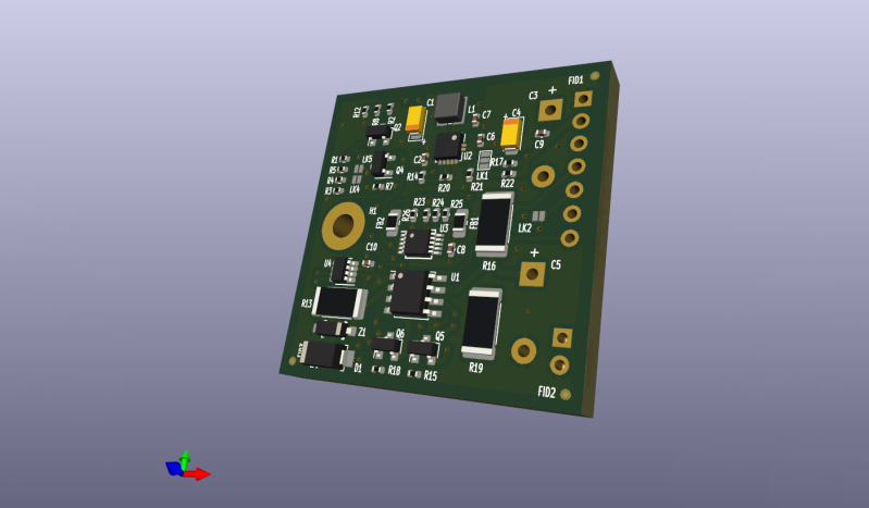
There are no actual photos – just computer generated images – and the “PCB layout” just shows component placement, no tracks.
Does it actually exist? Has the circuit even been tried?
Another pessimist who doesn’t read. There is a channel where you can see the live output of one that is running in the field now.
And clearly the 3D render shows tracking. You can’t expect something for free and have everything handed to you on a plate. Do some work yourself!
The tracks are there, but the front side is very faint due to the angle. this only the rough render in kicad, not the final shaded render afaik. but then again, it is on a hackaday.io site, not known for a optimum info troughput…
Yet another overcomplicated solution to a simple problem why use a get and a few parts when you can use an overcomplicated board to do the same job
So what is your solution, Genius?
What’s the benefit to using super caps in this application? I can’t imaging a LoRa system transmitting every 5 minutes is pulling much current during the Tx. Why go with this over battery storage? Last time I played with supercaps was in college and it was to bridge the Tx output draw that was well over what the batteries could provide.
Do they have a better lifetime or thermal range now compared to lithium batteries?
Been out for ages, have working units and have done for 5 years now. Solar one, Pathfinder lights ,MB by Trillium , Maxwell capacitor
What I’d love to have is a generic small PCB that we could stick into those 1$ solar garden lights in order to stick an ESP8266 into them.
Those lights are weatherproof, have a solar cell and a small nicd battery.
I think we’d only need a good boost converter which somehow knows how much energy the battery has accumulated from the solar cell, and only powers on the MCU if there is enough energy available to run it for e.g. 10 seconds.