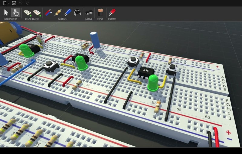
For basic prototyping, the go-to tool to piece together a functioning circuit is the breadboard. It’s a great way to prove a concept works before spending money and time on a PCB. For more complex tasks we can make use of simulation software such as SPICE. But there hasn’t really been a tool to blend these two concepts together. That’s what CRUMB is hoping to solve as a tool that allows simulating breadboard circuits.
Currently, most basic circuit functions are working for version 1.0. This includes passive components like resistors, capacitors, switches, some LEDs, and potentiometers, as well as some active components like transistors and diodes. There are some logic chips available such as 74XX series chips and 555 timers, which opens up a vast array of circuit building. There’s even an oscilloscope feature, plus audio output to incorporate buzzers into the circuit simulation. Currently in development is an LCD display module and improvements to the oscilloscope.
Besides prototyping, this could be useful for anyone, students included, who is learning about circuits without the need to purchase any hardware. The major downside to this project is that it there doesn’t seem to have a free or trial version, the source is not available, and it’s only for sale on Steam, Apple Store, and Google Play. That being said, there is a forum available for users to discuss problems and needs for future versions, so it’s possible that a community could build up around it. We’ve seen previously non-free versions of circuit simulation software become more open after some time, so it’s not out of the realm of possibility.
Thanks to [Thomas] for the tip!


Looks interesting but the lack of free desktop trial and odd targeting of mobile platforms puts me off. Anyway, I bookmarked the site forum to see what happens in the future, so thanks for the article.
I guess the mobile platform is practical when you want to recreate someting but dont have space on your workbench for a laptop or pc.
Hard to grasp someone doesn’t have a square feet on their bench for a laptop
I suppose you’ve not had a look at the desks of Bob Pease or Jim Williams, may they RIP.
The price is cheaper than buying a single breadboard, let alone all the components it supports. That said, I quickly got to a point where the simulation ran at 10Hz, but I was also half way through making Ben Eater’s breadboard 8-bit computer.
There is another similar application named Shortcuit, whose kickstarter sadly failed (and as such development is currently halted), but they have published a free demo on their website that’s pretty complete.
There are many more breadboard sims, like tinkercad and others.
It is available for Windows via a Steam download though.
Does the simulator really capture the full experience of circuits built on solderless breadboards?
It really should include:
1) the resistance when a component is inserted into the clip, due to oxidation/fluff etc, and springs pushed beyond their elastic limit by large wires inserted too many times
2) inductance of the wires causing Vcc an Gnd noise when a digital output switches
3) capacitance between wires
4) mutual inductance between wires (see the Tektronix 184 L69/L70 for an example)
5) the variation all those when somebody puts their coffee cup down or sneezes
Typically people spend more time debugging the solderless breadboard than debugging their circut. Just Say No, and use manhattan techniques
I give up chasing through the internet.
What is the manhattan technique? Presumably it is not manhattan wiring.
https://hackaday.com/2016/05/04/getting-ugly-dead-bugs-and-going-to-manhattan/
Lol yeah, soldering everything together is much easier. Why not debug your solderless breadboard as you build? It’s not hard. If freshman college students can do it, you can too!
As a dev trying to learn electronic, there should be like 3 levels of simulations (4 with you idea?)
The noob one, you are in a perfect world.
The usual world. Those button presse will screw you up. That breadboard has capacitance…
The let be a bitch (component are more sensible?)
And maybe that “FML” where you have ElectroBoom is messing around while you use rusted part with a Chinese Walmart, no regulator, and cloned part!
That’s not how real life works. Get off youtube.
Well, out of the hands on experience, a functional circuit in a software that is the close thing to a well built PCB soldered one is not better than a glitchy breadboard simulation?
Hahaha, I remembered the good old days, everything works just fine in the simulator and nothing works on the protoboard 😆
Are there any of those simulators that I can plug a virtual arduino (esp32, raspi, ….) in and run code for the I/Os? I think that would be neat :D
Oh, apparently this one does include arduinos (according to some forum entries in the desktop version at least). So maybe I should check it out :D
Have a look at https://wokwi.com/
Tinkercad. By Autodesk. I’m a teacher and use this for teaching the breadboard basics and Arduino basics from 14 to 18 years (A levels) It’s limited by the component range but it has a surprising amount of fun stuff. Ultrasonics, addressable led strips, h Bridge IC, servos, steppers, rotary encoders, lcds (Inc 4 wire variants with i2c) . The default ‘block coding’ is a bit limited, but it also supports regular c type arduino coding.
This is one of those things that would greatly benefit by being open source (well managed of course) because of just how much could (and should) be added to it. I’m impressed with it but at the moment it’s relatively limited and one guy is going to really struggle to make it what it could be.
One word. Fritzing.
One word:
Nooooooooooooooooooooo!
A version on the Google play store but not for Chromebooks.
There’s an opportunity missed considering the number of Chromebooks in education.
The *idea* is not new… even for the 68000 Macs there was a breadboard simulator, way back in time.
I remember “wasting” some of my time with it ;-)
https://www.macintoshrepository.org/25302-macbreadboard
Old is the origin of new ideas,therefore don’t regret the time you spent on it those old good days.
I thought of this concept 30 years ago. At the time, to my knowledge, this application didn’t exist. Where I can see the advantage of simplifying circuit design via snap in, modular, known circuits, I can’t see how it could help develop the modular components themselves as their i/o would only be theoretical. I also don’t see where the all important heat buildup and its effect on the circuit i/o as well as the components themselves is, or could be, simulated
In my development cycle, this is the FUNCTIONAL prototype, which allows for approval of the concept and functionality – this ensures the final design for product approval – the PRODUCTION prototype – will be as close to what was intended as possible.
Both levels of prototype often need several passes of debugging and approval before making a hundred or a million units !