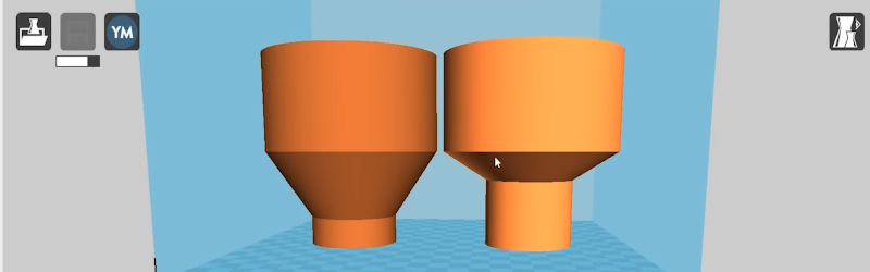
If you want to 3D print arbitrary shapes with an FDM printer, you often find you need supports. If you have dissolvable support material, that might not be a big issue, but if you use the same material for support as you print in, removing it can be difficult, depending on the location of the support and your slicer. At the very least, it is going to require more time and filament to print and at least some post-processing. [Slant 3D] asserts that you can always redesign the part using chamfers and fillets to avoid needing support to start with. Watch the video, below.
Of course, sometimes you just need to flip the part around. For example, the part in question — which is just an example — could just be rotated to avoid support, but that isn’t the point, of course. A fillet, however, still might need support, so you wind up having to do a double fillet to really avoid support.
The answer, according to the video, is a chamfer. The steady change in angle is easy to print, although not all designs will allow a steep chamfer. So picking the angle is the key and you might even mix both chamfers and fillets.
Creating chamfers and fillets might be easy or difficult, depending on your CAD package of choice. OpenSCAD is notoriously difficult to add these things, but you can use FreeCAD which can interoperate with OpenSCAD to make it easier. There are also a number of libraries available. Speaking of FreeCAD, we saw that tool used in another method to avoid supports: print flat and fold.


I use Openscad (O) and Cura (C).
Want to have an infill with different density at certain point? Create multiple overlapping models in O, export in 3MF and import in C with different setting. Cumbersome, but works.
Handling individual support structures in C? Never managed it. The menu stuff in C is totally messed up. I just design in O around the problems in C.
I would love to switch to different tools, but the either want my money, than change their business model (and want more money, went out of business or are sold to some other after some time).
Or they are to difficult for my small brain to graps the concepts…
So I would love to see a discussion about a tool chain that is simple, for simple minded (ok, that is a bit of an understatement, but really, I’m I want to be stupid most time of the day), not that expensive/free/open and still there in 5 years.
Freecad ?
No. It has a horrible GUI. starting with it’s micro fonts and non-screen-adapting-gui that does not work good with my eyes (and is, mildly talking, a very outdated concept).
Then I gave PartDesignExample some tries. First add a rounding/curve into two intersecting surfaces at its “toothie section”. It should be easy: select those two surfaces, “construct rounding” (or whatever), done. I found nothing beside rounding everything. And lists of stuff with numbered names….
Then I wanted to drill a hole into the lower body. Again, it should be middle easy: select the surface, select some cylinder… Naaaa. Nothing for me.
There might be ways how to do it, but Freecad looks like 1980s are coming back… I don’t want to work that way.
FreeCAD works for me. It takes time to learn (like any CAD environment does), default styles aren’t good, and OCC is great at best and horrendous at worst. (95-5 split there). If you don’t like the graphics, select a different view. UI? Install an addon to change looks. It even includes OpenSCAD as a workbench.
So far the most useful thing about it is that it works offline, is somewhat graphical, and has built in FEM.
Hole is “select the surface, drop into the sketcher where you can actually constrain the hole location in some meaningful way with geometry and dimensions rather than typing in arithmetic expressions, then tell it to make holes out of the circles in the sketch”. The “cube with an edge pulled out” button lets you pull existing lines in the object into the sketcher and use them like construction lines.
It’s definitely geometry-oriented more than absolute-coordinates-oriented.
For the rounding you unselect the default of “everything”, then click “add” and click the edge you want rounded; the numbered-items list and picking with the mouse work together. Way easier to pick an item from the list to delete it than having to find that edge in a complicated part. What’s more annoying is that you do need to keep the old surfaces, you can’t fillet them _entirely_ away or the operation fails.
On the whole, the biggest shift for freecad vs. openscad is that you should expect to be in the sketcher directing it with plane geometry a lot, with a few things you then _do_ with the sketches to define the part geometry like pad, pocket, and positive and negative revolve. That’s how the spendy ones – certainly solidworks, fusion 360, etc – work as well, at least for designing things that do stuff rather than sculpture.
The FreeCAD GUI is indeed win2k-ish-ugly by default, but does not appear to be excessively tiny fonts on a 4k screen, although I do wish there were a way to adjust the size of constraint icons in the sketcher in the default build. It was previously on an older pyQT, though, so if it’s been a while it might be less misbehaving on current versions.
A lot of the reason FreeCAD gets so much recommendation is because it’s just about the only option, and certainly one of the oldest continuously-developed ones, that’s the same kind of program as the big cad systems, rather than some reimagining of how to do cad.
That said, cadquery is the same “real cad” kernel underneath but a more openscad-like interface, and may be worth a look.
Sometimes I just split the par in two sections along the offending area flipping one part upside down. Then glue together afterwards… I use tinkercad. ..
There is a FreeCAD branch called RealThunder. Big improvements to UI and technical stuff. I won’t go back to the main branch FreeCAD now that I’m used to it.
https://youtu.be/qPoFrgk8S2U
Have you considered trying modifiers in Slic3r/Prisaslicer/Superslicer?
You can apply a modifier as a primitive you define in the slicer, or import it as another mesh with the same origin. The area of the mesh that falls in the modifier can then have different parameters, like different infill, perimeters, or even materials. And the entire project can then be saved as a 3MF file, that will store the plate information in metadata.
We really be making videos and Hackaday posts about chamfers these says.. :D
OR, turn it upside down so there’s no need for support. Not the best example honestly.
Did you try reading the text?
Watched the Video. I do resin printing and flipping items around to eliminate or minimize overhang has worked wonders for me. I admittedly don’t do filament prints.
turning it upside down without changing any geometry just moves the overhang to the inside where it’s harder to print.
“Never use 3D printed supports again” night be a bit of an oversell here. You can design to avoid and minimize support in a lot of situations but sometimes something just has to be how it has to be and support is the way to get it done.
I usually design my parts without having to use support if possible, and if support is really needed I design them into the model itself, not having to rely on inefficiently generated support. That can eat up printing time and material.
Try DesignSpark – its free and fairly intuitive. Chamfers and fillets are a doodle.
I used this technique to remove supports here:
https://mstdn.ca/@donbarthel/109462472912188039
I just designed a system of ski vises, including some tricks to avoid problematic overhangs.
https://www.printables.com/model/329794-ski-vise
Some of my favorite tricks are chamfers and splitting parts for convenient printing. Less well known is using a thin sacrificial layer to bridge unsupported countersinks, as well as some very short recessed steps in the overhangs which also avoids turns while printing unsupported features. Basically the overhang is split into several vertical layers using a rectangle and a square. Straight runs supported on both edges generally print well, so hex and circular unsupported overhangs can be split to allow straight line travel across gaps. Combined, these allow for great internal overhangs.
MakersMuse has some fantastic videos on this subject. Many more tips than just “use chamfers” (fine, it’s in there, but not the only one).
https://www.youtube.com/watch?v=RPijCjz9G1w
https://www.youtube.com/watch?v=SBHHwid7DWM
https://www.youtube.com/watch?v=FzCm1iTf8PA
I’ve gone full circle on this over the years. Support generated by [insert slicing tool here] is invariably a nightmare to remove and you never need it everywhere it gets put.
Obviously design out overhangs as much as possible, but if you need support, design it into the model. A couple of pillars here and there separated by about 0.5 or 0.6 mm from the surface they’re supporting do the job fine and snap off easy. Or if there’s a big aperture I want to support I’ll put a stack of thin plates in there, again 0.5mm gap all around, and punch them out.
Really easy to do in sketchup. Slightly harder in FreeCAD because you either need multiple bodies or, as I do, leave tiny ties between them so it’s one body. But still not that difficult and much more reliable.
Great idea!
Sometimes the overhang is in an object and that’s where the support material is near to impossible to get out. I recently designed a small catch that needed a freely rotating axle that was printed inside the catch and had to be held in. I initially thought I might be able to get away with a support but was proven wrong as if it has nowhere to go it just stays put. it was worth a try but I then did the 45 degree angle under and above it and all is fine. It’s a neat way of solving it and I didn’t have to leave openscad to do it.
https://donnels.github.io/openscad-examples/README.html#_fastener_3d_object
$fn=100;
mainLength=50;
mainD=15;
mainH=10;
axleD=10;
axleDout=axleD+3;
ringH=2;
magnetX=17;
magnetY=5;
magnetZ=2;
module axle(xxlX,xxlY) {
translate([0,0,-xxlY/2])cylinder(h=mainH+xxlY,d=axleD+xxlX);
translate([0,0,((mainH-ringH)/2)]) cylinder(h=ringH,d=axleDout+xxlX);
translate([0,0,(mainH/2)-((axleDout-axleD)/2+ringH/2)]) cylinder(h=(axleDout-axleD)/2,d1=axleD+xxlX,d2=axleDout+xxlX);
translate([0,0,(mainH/2)+(ringH/2)]) cylinder(h=((axleDout-axleD)/2),d2=axleD+xxlX,d1=axleDout+xxlX);
}
the XXL variables are to create the space required around the axle. The rest is just addition and subtraction and creating a 45 degree angle is as simple as making the vertical the same as the radius of a cone so that it more or less jumps out as the easiest solution right of the bat. If it was outside and visible it might make sense to apply cosmetics also but for a part that’s inside another part the 45 degree angle is more or less perfect.