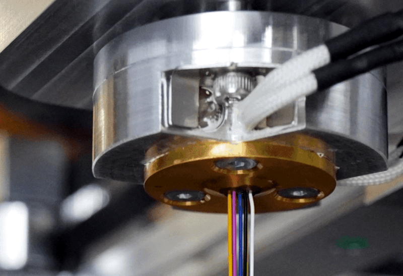
The problem: you want to produce varying line thicknesses when 3D printing. The solution, if you are the Liqtra company, appears to be to put seven print heads together and enable one for thin lines, all of them for thick lines, and something in between for everything else. The technical details are scant, but from the video below and some pictures, you can get a general idea.
There are some obvious benefits and drawbacks. You’d expect that for the right kind of part, this would be fast since you are essentially laying down seven tracks at once. The downside is your track width varies in pretty course steps, assuming you have to use the maximum width of each nozzle to prevent gaps. New slicing software is a must, too.
The demos and pictures show multiple filament colors because it photographs well, but you’d assume in practice that you would use seven spools of the same material. The good thing is that you could print with a single nozzle where that’s important. We assume all the nozzles are the same size, and that will control the practical layer height, but that’s a small price to pay.
The company claims a much faster print, but as we mentioned, this will depend on the specific printed part. They also claim inter-layer strength increases as well, although we found that surprising. This is probably overkill for home users, but we imagine this would be an interesting technology for people trying to run production quantities through a printer.
We don’t remember seeing this approach with a homebrew printer, although having multiple extruders into one or multiple nozzles isn’t unusual anymore. It seems like you could experiment with this kind of technology pretty readily. Of course, there’s more than one way to speed up production.


Why do people like these vertical short videos that don’t allow you to properly control them?!?!?
Because idiots live their lives a smart phone and rotating the phone has historically proved too difficult. *sigh*
Certainly doesn’t have anything to do with the platform mandating certain viewing standards in order to be promoted by the algorithm.
Nope, you’re right, its ALL the fault of the content creators. They’re just idiots.
You misunderstood, the content *consumers* are idiots. Can’t argue with that.
Even for a single fixed nozzle, line deposit width is variable by varying flow rate (which is driven by filament feed rate, and limited by motor and heater power, layer thickness, and to some extent by nozzle diameter and other flow restrictions) from a minimum of around the nozzle exit diameter upwards.
Yes, but not nearly to that extent. If you had, say, 0.8 nozzles you could lay down well over 5.5mm of plastic in one go, I would think. But I also think you could not do much variability per nozzle unless you were in one nozzle mode because you don’t want the thick lines to overlap or underlap (is that a word) more than whatever is normal for adhesion.
Would an iris/rotary diaphragm work well for this?
Probably not. I would expect it to gunk up and jam up in very short order. Nor do I suspect they’d deal with the extrusion pressure very well.
I think it might be easier to drill a bunch of holes in a line, and then rotate the head to expose more or less of the width of the line, while having extruder feed a function of the rotation. That does add some mechanical complexity, in that you’d probably have to swivel the whole head. But it would be easier to manufacture the nozzle, at least.
and use a material ,with longer curing time/lower temp before hardening, in the middle nozzle ,it could improve layer adhesion , it would still be sticky/soft , when next layer comes by, but can go nowhere, because it would be “gated” by the outer strings in the “sandwich
I am thinking something more resembling wire strippers. Eg. two opposing v-grooves geting closer and further apart… not sure how to make it manifold tho…
I like the concept but the implementation does not lend itself to the DIY crowd.
That nozzle is not always going to have replacements available.
Heyyy, we’ve come full circle and now we have dot matrix print heads for FDM!
I suppose that if you star using a nozzle and then stop it extruding it will keep oozing a bit. They are all in the same plane that was the issue with multi nozzle hotends like the E3D Kimera.
I haven’t done any 3D printing, but I’d think a variable width nozzle would work better. Like a slot, maybe 5mm wide, with one end controlled by a stepper so you could control the width of the opening. So, “closed”, you would get a .5mm x .5mm strand. Open it up all the way and it would be .5mm x 5mm ribbon.
I’m sure there would be issues to work out (like gumming up) along withe the same “new slicer” software issues.
Coarse != Course
Nothing wrong with a more geometrically simple nozzle with an oval opening and a motor that rotates it, is there?
I recently needed a similar thing for a scissor lift mechanism and needed the absolute position of a lead screw with a movement of 200 mm in length. I used a belt and pulley to drive a multiturn potentiometer to get the resistance. This I then use to make a kind of linear servo with range of 200 mm . The sensor is actually 20mm in diameter and 30mm in height and occupies a lot of space.
wrong place to comment
But if the Earth is really flat, does the gravity effect the pull of the material or is a density behavior?
LOL. hackaday should be a space for crazy scientists not for companies. I never expected that. Were is the next crazy scientist with the big idea for an open-source variable size nozzle?