
Last time, we configured the FUSB302 to receive USB PD messages, and successfully received a “capability advertisement” message from a USB-C PSU. Now we crack the PD specification open, parse the message, and then craft a reply that makes the PSU give us the highest voltage available.
How did the buffer contents look, again?
>>> b
b'\xe0\xa1a,\x91\x01\x08,\xd1\x02\x00\x13\xc1\x03\x00\xdc\xb0\x04\x00\xa5@\x06\x00<!\xdc\xc0H\xc6\xe7\xc6\x00\x00\x00\x00\x00\x00\x00\x00\x00\x00\x00\x00\x00\x00\x00\x00\x00\x00\x00\x00\x00\x00\x00\x00\x00\x00\x00\x00\x00\x00\x00\x00\x00\x00\x00\x00\x00\x00\x00\x00\x00\x00\x00\x00\x00\x00\x00\x00\x00'
The zeroes at the end might look non-significant, and they indeed are not with 99.99% certainty – that said, don’t just discard the entire tail end; one of the bytes in the beginning encodes the length of the message. We’ll read those bytes first, and then read only exactly as much as we need, making sure we aren’t reading two messages and interpreting it as one, and that we’re not discarding zeroes that are part of the message.
Today, we will write code that parses messages right after reading them from the FIFO buffer – however, keep this message handy for reference, still; and if you don’t have the hardware, you can use it to try your hand at decoding nevertheless. If you wanna jump in, you can find today’s full code here!
Header Parsing
The first byte in the buffer is 0xe0, and it’s not actually part of a PD message that we need to parse – it’s a “start of a message” token, and you can find it in the “RX tokens” section in the FUSB302 datasheet page 29. If you’re looking there and don’t know what SOP is – for our purposes, SOP (without ' or " at the end) means “this packet is for a device at the end of the cable, and not inside of the cable”; we are, indeed, at the end of a cable and not inside one. Further bytes are, however, a meaningful part of a USB-C packet, and that’s where you want to open the PD specification.
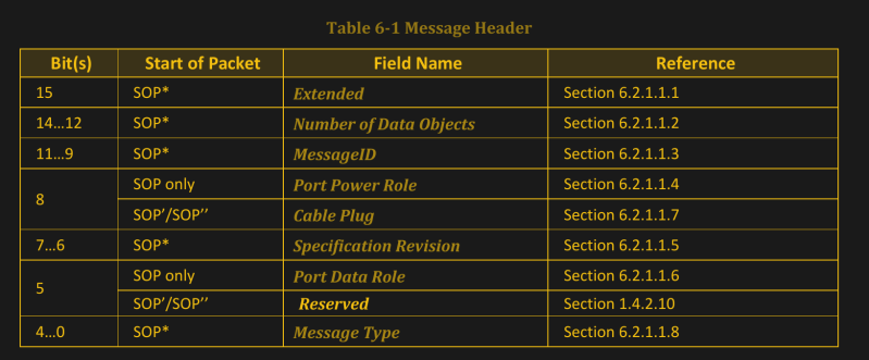
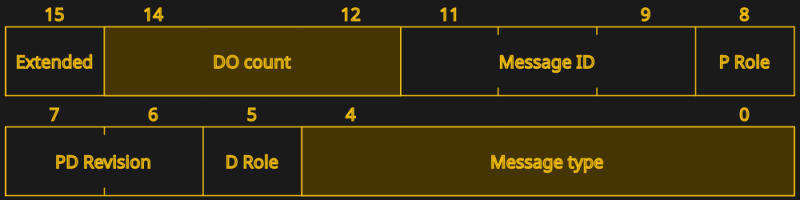
The header is described in the PD 3.0 specification section 6.2.1.1 – page 109. It’s two bytes: in our case, it’s the \xa1a part of the Python’s bytearray representation, 0xa1 0x61 in hexadecimal and 0b10100001 0b1100001 in binary. The first byte contains bits 7-0 and the second byte contains bits 15-8 – you could say, each part of a PD message comes in backwards. The main part we care about is bits 14-12 – take the second byte, shift it right by 4, and mask it with 0b111 to get the message length. In our case, (0x61 >> 4) & 0b111 equals 6.
If the message length equals zero, we have received a control message – those are described in section 6.3, on page 119 of the specification. In the example message, the length is 6. This is not an number of bytes – this is the count of PD data objects, also known as PDOs (Power Data Object). Each of them is four bytes long, and in our case, each of them corresponds to a PD profile. Plus, there’s a CRC at the end of the message, which is four bytes. Thankfully, we don’t need to verify the CRC – the FUSB302 has verified the CRC for us; if the CRC weren’t correct, it wouldn’t put the message into the FIFO for us to read in the first place.
How many more bytes do we need to read, then? We’ve already read three bytes, determining that we have to read six four-byte data objects, and then a four-byte CRC. In total, this message is 31 bytes long. Let’s read the objects first, then read the CRC and discard it. The easiest would probably be reading out of the FIFO four bytes at a time – I’ve read the entire PDO and then split it into messages afterwards in my own implementation.
Getting The Power Profiles
pdo_count = 6
pdos = []
for i in range(pdo_count):
pdo = i2c.readfrom_mem(0x22, 0x43, 4)
pdos.append(pdo)
_ = i2c.readfrom_mem(0x22, 0x43, 4) # discarding the CRC
Now, we have a list of not-yet-parsed power profiles in pdos – I’ll refer to them as PDOs for brevity. Here, you would do good writing a separate function to parse a PDO, if not for readability reasons alone.
The data message format is described in section 6.4 of the specification, page 129. The first thing you check with a PDO is the data type, bits 30-31, or bits 7-6 of the last byte in the PDO as we receive it. There are four types possible – fixed (the most popular one), battery and variable supply, and the augmented PDO type. We can limit ourselves to processing fixed PDOs for now, and safely ignore the other types.
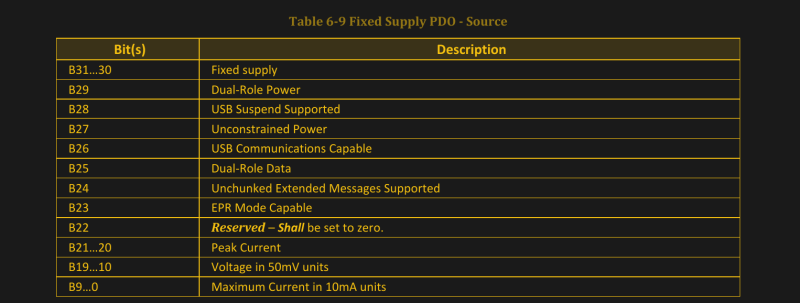
If you start parsing the PDOs already, you’ll notice that we have five fixed PDOs and one extended PDO. I’ll say that this does match the marking on the USB-C power supply I received this message with! Let’s go through the PDO – see page 132 for the table 6-9; it is a very nice table and it has everything you could need. Let’s parse it for the first PDO.
00101100 10010001 00000001 00001000
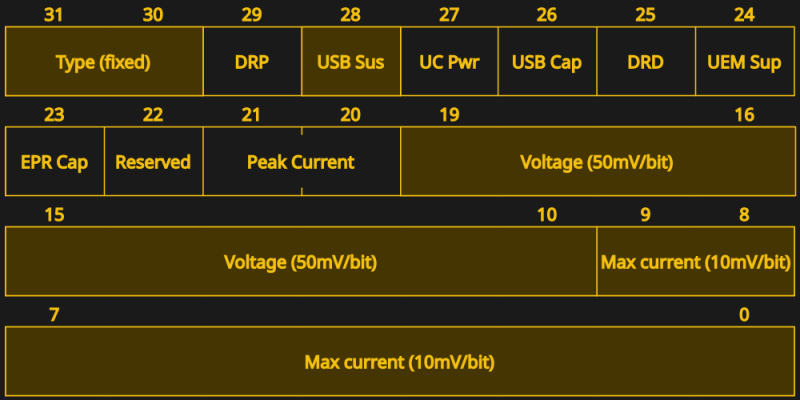
Maximum current is bits 0-9 – so, the two last bits of byte 1, and then the entire byte 0. Voltage is bits 19-10 – four last bits of byte 2, and six first bits of the byte 1. If this is painful to read, refer to this piece of code that parses PDOs in Python. After getting the voltage and current numbers, multiply the voltage by 50 and current by 10, to get millivolts and milliamps respectively.
>>> 0b0100101100 * 10
3000
>>> 0b0001100100 * 50
5000
Oh would you look at that – we’ve got 3000 and 5000, which, as you might’ve guessed, means 5 V at 3 A. PDO parsing function for this part can be found here.
Requesting A Power Profile
Now, we have the PDOs – from 5 V all the way up to 20 V. To ask the PSU for one of them, we need to craft a Request message. And remember – to actually get the PSU to provide a higher voltage to us, we need to send our response fast, before the PSU timeouts waiting for a response. Let’s, then, write a function that crafts a response and can automatically reply with it. It’s a four-byte message, with a two-byte header – let’s make a list of six zeroes, modify them in place, and then send them out. Something quick and dirty like pdo = [0 for i in range(6)] will do wonders.
For a start, let’s refer to the header specification – now we actually have to read through fields in the message header and set the ones we need. Again, section 6.2.1.1, page 109! For bits 15-8 (pdo[1]), we only need to change the number of data objects. In our case, it’s 1 – we’re sending a data message with a single PDO request message inside of it. For bits 7-0 (pdo[0]), we need to set the specification revision (bytes 7-6) to 0b11. We also need to set the data message type in bytes 4-0: see the table 6-6 at page 128 for that; in our case, it’s a Request message, with code 0b00010. Oh, and there’s a “Message ID” field that we can now leave at 0, but that you’ll want to increment for subsequent messages. This is all we need out of the header – now, let’s craft the actual request in the four remaining bytes.
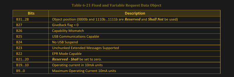
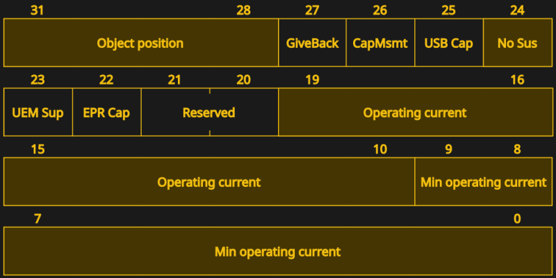
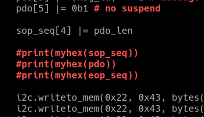
Request messages are described in section 6.4.2, page 141 – you’ll want the table 6-21. In order to request a PDO, we need to know its index – and increment it by 1 before sending. So, 5 V @ 3 A is PDO 1, 9 V @ 3 A is PDO 2, and so on. Let’s go for the 9 V PDO and put 0b010 into bits 31-28. The USB-C PSU will also want to know the maximum and average current we actually plan to consume. Since we’re experimenting, let’s ask for something like 1 A, setting both maximum current (bits 9-0) and operating current (bits 19-10) to 0b1100100. You will also do good setting bit 24 (bit 0 of pdo[5]) to disable USB suspend – just in case.
Now, we have a message! However, we can’t just stuff it into the FIFO. We need to prepend and append two byte sequences that let the FUSB302 know what’s up, known as SOP and EOP sequences (Start and End Of Packet respectively) – consult the FUSB302 datasheet page 29, again. The SOP sequence is five tokens long and essentially transmits a message preamble – three SOP1 tokens, one SOP2 token, and one PACKSYM token; we need to OR the PACKSYM token with our message length in bytes, six in our case, making it 0x86. The EOP sequence is JAM_CRC, EOP (token), TXOFF and TXON. Why these exact sequences, I don’t quite understand, but I’m quite glad I have some open-source PD stacks that I could copy this behaviour from. So, 0x12 0x12 0x12 0x13 0x86 before the packet, and 0xff 0x14 0xfe 0xa1 after.
SOP sequence, packet, EOP sequence – put them all into a FIFO, and we’ll have sent a Request message. The overall worfklow is simple – get capabilities, parse capabilities, pick the one you like, create a Request message, send it, get your voltage. The payoff? You get the voltage of your choice.
A Smidgen Of Debugging
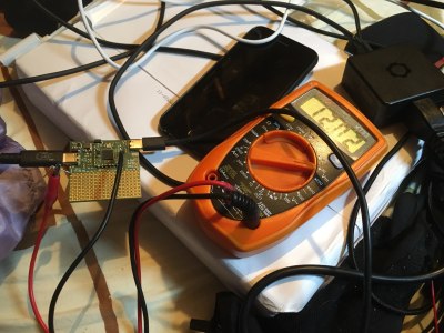
If we didn’t miss anything, probing VBUS will show that you’ve successfully extracted the 9 V profile we agreed to try. If you’re experiencing any hiccups, again, here’s reference code in Python that you can use, and here’s an I2C transmission reference for the Pinecil. Having problems? Here are a few tips.
As is usual with debugging, print() statements will help you quite a bit, until a certain point. On one hand, they’re indispensable, especially if you’re meticulous about converting data to binary or hex representations depending on which one is the most helpful at any debugging point. For instance, you can print the entire packet in hexadecimal, and then print PDOs in binary so that you can check your parsing code.
On the other hand, print() statements will interfere with the timing requirements to a surprising degree. Sending data over the console takes a whole ton of time – even if it’s a virtual console, as is the case with the RP2040’s virtual UART over USB-CDC. I’ve spent about two hours debugging this code on a RP2040 and hitting the timeout window all the time, only to find out that I had twenty print statements, and they singlehandedly brought my code from “really fast” to “too slow to respond”. After I commented out the print() statements, my code started working on every PSU I tried it with, and I tacked on a whole ton of custom voltage and current selection logic without any problems.
Checking the receive buffer contents is also useful. After you’ve sent your request, check the receive buffer state – just like in the end of the last article. Is there some data waiting? Read the message out of it, and check the header – is it an Accept message? Refer to page 119 for the code for that one. Nothing in the buffer after a request message? You’ve likely violated the timing requirements.
On the other hand, it’s pretty hard to write MicroPython that is slow enough to violate the timing requirements here. As you make the script more complex, it might be that you spend too much things between receiving the PDOs and sending back a response. Or, perhaps, you get a different kind of message in your receive buffer? Your PSU might be sending out some other message that requires a quick response – perhaps, you’re working with a laptop’s USB-C port, and it wants something else.
9 Volts Reached – What’s Next?
 What we’ve done here rivals a PD trigger board in price, it’s way more customizable, likely as cheap if not cheaper than a PD trigger IC, and undeniably way cooler. Oh, and we’ve learned to read and send PD messages – which can and will help you if you’re ever interested in creating anything out-of-ordinary with USB-C. All you need is a FUSB302 chip (about 50 cents apiece), paired with a microcontroller that’s dedicated enough to the task of talking PD – you might already have such a MCU in your project doing something else.
The code is in MicroPython; that said, it’s pseudocode-y enough that it’s easy to port it to a different language from here. If you’re running C++ or C, check the IronOS stack; there’s a STM32 HAL-suited one, an Arduino-suited one, and there’s a decent stack from Microchip. I’ve only seen the former in action; yet, if you don’t feel like MicroPython, I’d wager one of them will be right for you.
Something that you might’ve noticed – at no point did I have to refer to the spooky USB-C state machine diagrams. There are a few states in this code, technically, and state machines are great enough that this code would be improved with one if it were to grow more complex; however, you really don’t need one if all you want is 9 V from a USB-C power supply. The spooky diagrams can, however help you debug things like the 500 ms advertisement-to-response timeout – in other words, don’t be afraid.
From here, you can do a lot of things USB-C. You can turn your barrel jack power supplies into USB-C ones with a bit of extra circuitry, make a supply with wacky custom profiles, explore hidden capabilities of PD controllers, get DisplayPort out of USB-C ports – hell, if you’re pentesting-inclined, you can even create malicious USB-C gadgets.
Here’s my personal simple hack – a short algorithm that picks the best PDO for a static resistance value while keeping maximum current values in mind; solving exactly the scenario where a trigger board fails us. It ties perfectly into the code we’ve written so far, and if you want to develop a high-power USB-C device that does something similar, it might be of interest to you.
You can, and should approach USB-C in a hacker way, and this article is a great example that you don’t need the entire complexity of USB-C PD standard if you want to do useful things with PD – all you need out is ten pages out of eight hundred, and a hundred lines of code.


It’s a barrel jack and buck converter life for me.
Thank you for this interesting and informative series about the inner workings of USB C. I could never have read that 400 page beast of a specification.
400 pages. Sir that is only one part of the standard. There are many many 400 page specifications that define USB C
I’m reading them right now as part of my work. And yes, it’s no fun! But this series of articles helps a lot!
What bothers me the most is that via the CC lines not only the power delivery is controlled but also how USB data works. Who is taking the host and the device role. Check out DR_SWAP and PR_SWAP commands.
Thankfully, the roles assumed by default are pretty reasonable – power sink is device, power source is host. Now, yeah, if you need to a “sink+host” arrangement, you do need CC communications – thankfully, not much, the DR_SWAP flow seems to be simple enough!
It’s not many – I’ve only ever referred to two. The Cable&Connector spec is 400ish pages, I’ve gone through it within a few hours’ time, and it has plenty of situational stuff of the “how to build optical USB-C cables” kind, that you can just scroll through. The PD spec is 800ish pages, and again, there’s a ton of stuff you can scroll through – for these two articles (aka, “implementing your own sink”), I had to refer to like, 10-20 pages of the PD spec overall. My experience has been – you don’t need to religiously study the spec nowadays; there’s plenty of stuff online, like example implementations of different complexities, appnotes that chew through the spec and present it to you from different angles, and plenty of chips that will do simple and complex tasks for you.
>you don’t need to religiously study the spec nowadays; there’s plenty of stuff online, like example implementations of different complexities
That just means errors propagate and assumptions that were fine for other use-cases get applied incorrectly – you have to understand the spec fully enough to know that example is suitable and sane!
A spec really MUST be simple enough that you don’t need a few days taking notes on the tomes that define the spec to set all the various layers of it straight in your head and half a tree to print it. And it really SHOULD be stable and sanely named enough that you are not chasing moving goal posts on the spec with no clear identification of which version you actually designed around. Which USB has be awful with as a rule for ages now, I’d swear their naming conventions and marketing teams are deliberately trying to make shit impossible.
I’m speaking from experience here – the hacker-friendly way to approach things absolutely doesn’t “just” mean error propagation, you’re missing a large part of how knowledge sharing works in real life. As time passed, we compensate for errors we would’ve been making initially – as an example, nowadays, there’s plenty of people that can readily point out lack of 5.1k resistors in your USB-C device port, and explain what it implies. This principle applies to many things in life. You don’t have to get a PhD in a language to speak it somewhat well or even proficiently – it’s more than enough that you study some, and most importantly, interact with other people that speak the language.
The “specifications MUST be simple” is just not realistic – some things should not and cannot be simple, and we’ve learned that the hard way over the years. There’s a ton of complex things in electronics and day-to-day tech that we rely on by now, and most of them are quite worthwhile despite the complexity – like, damn, you sure you’re not relying on a WiFi, LTE or Ethernet connection to write this comment? As hackers, we deal pretty well with complex things – we learn through exploration, find shortcuts and ways to work with a complex technology, and share our understanding of complex things distilled in different ways from different angles; this is all part of why people like articles like these. Say, if you want a simple bus for PC peripheral interconnect, you can personally always come back to ISA hardware – but mind you, there’s a myriad of good reasons we use PCIe nowadays, even given it’s thousands-of-pages complexity; what we get out of it is ease of use, high speed, versatility and a large degree of design-friendliness. Mind you, PCIe hasn’t always been smooth sailing, either.
I understand USB-C pretty well, and it didn’t take anywhere near the large amounts of effort or some thought-up scenarios you’re talking about – and, given that all twelve USB-C article to date have a rant from you in the comment section, I’m not sure you’ve been going the productive way about dealing with it! In summary, I diagnose you with “hack moar” 😝 Perhaps then you can relate to the principles of why things deserve to be complex, and how we hackers ought to go about such cases!
>The “specifications MUST be simple” is just not realistic – some things should not and cannot be simple,
OK so read it ‘SIMPLE AS POSSIBLE’ – keep it simple and elegant over a bloated ever growing mess!!!!
Those reference coping issues do mean errors propagate – if not then you wouldn’t be finding so many things lacking that 5.1k resistor for instance – they all copied the same flawed idea. It might get fixed for future referencer, but equally they can still happen to pick up on the old and ‘wrong’ implementation – all down to where they got that reference circuit. And with how much of a moving target USB-C and PD have been future mistakes of using old but actually good at the time references are inevitable.
And if the spec was sane and simple you wouldn’t find that so many folks in giant companies with huge resources and experienced staff put into design and refinement of their products missed the fact it should have been a requirement for their device, but actually it was working fine for them as it only is for certain types of USB device combinations, not all of them that will fail…
PCIe is massively massively simpler – and has to be as USB-C effectively contains much of PCIe inside its massive bloat not the other way around.
I have nothing against complexity when it actually makes sense for it to be that way!
Or in short
There is a huge difference between the required complexity to actually get a functional result and excessive complexity because at no point has anybody actually tried to make it a concise effective spec. USB-C has just been ‘throw another 100 pages ontop to deal with this, that and the other new idea’ – never taking that moment to think how stupidly surplus to requirement ‘this and that’ could be.
I get that you consider it a “bloated ever growing mess”, but this assessment is seriously hard to relate to. I have USB-C work for me pretty damn well day-to-day, and when I explored it, I’ve found the complexity to be warranted – plus, I’ve found tons of ways to keep things simple. In other words, I’ve found the “As simple as possible” to apply well here. Nowadays, when USB-C goes wrong for me, it’s invariably manufacturers being ignorant or malicious wrt pulling proprietary bullshit. And, when it comes to you specifically, the ongoing negative comments coupled with factual errors make it pretty hard to take you seriously.
> all copied the same flawed idea.
No evidence that anybody copied anything as a trend – the “lack of resistors” mistake is of the kind that manufacturers make on their own, due to lack of simple research (loads of appnotes for “how to add a USB-C device port”!) and testing. With lack of resistors, you can typically sense that someone replaced a microUSB connector with a USB-C one and didn’t look any further. There’s no resistor-less “reference implementation” I know of, but you can be certain that laziness is a constant in cheap device manufacturers.
> so many folks in giant companies with huge resources and experienced staff put into design and refinement of their products
Overwhelming majority of USB-C devices I’ve touched, work, and as such, it’s hard for me to take this as anything other than negativity bias. In cases where USB-C doesn’t work, “giant companies with huge resources” is an exception (i.e. Dell with their intentional proprietary BS); so your “so many” is counterfactual.
> PCIe is massively massively simpler
Lol, the 5.0 spec is 1,299 pages (yes, fifth revision, ‘ever growing’ too!) and there’s a load of documents to go with it. “M.2 For Hackers” took me three articles alone. Are you, sure?
> as USB-C effectively contains much of PCIe
This is outright wrong. The closest thing is “USB-C can support Thunderbolt altmode, which can optionally tunnel PCIe”. Ngl this makes me half-seriously wonder if you’re ChatGPT or something – it also doesn’t bother making sure what it states is actually true 🙃
> throw another 100 pages ontop to deal with this
That’s absolutely not what I was met with, when, again, actually reading and implementing the spec. Like, look at it this way – I’ve worked with USB-C, I’m using USB-C in large amounts day-to-day, it works seriously well for me, and I just don’t see you engage with that the way I’ve been engaging with your comments. Twelve articles in, it’s become pretty boring to talk to you, especially seeing you stuck on a few overall insignificant points like “spec is way too complex” that I flat out can’t relate to. I see you having grievances, but I absolutely don’t see you knowing what you’re talking about.
All I meant was being able to tunnel a PCIe Signal requires USB-C to match or exceed the electrical requirements of PCIe signalling! Thus it must contain effectively a portion of PCIe specs or be sure to meet or exceed that requirement via other means!
There are just so many stupid design choices in USB-C that cause no end of headache for a great many people and heaps upon heaps of devices are crap because of it – or so it seems to me and quite a large number of folks on the net. Just not happening to you (lucky you) – which is probably why you are finding it so easy to love USB-C, as when it works properly it can be very nice to use, just one cable, so convenient.
Also you write 3 articles on M.2 and how many on USB-C now?? Even if you cut out a few as being less about USB-C and more the device in question its a substantial volume more writing, to not even finish laying a complete groundwork for USB-C yet…
[Foldi-One]: The idea of tunneling PCIe over USB 3.0 really breaks the idea of both PCIe and USB. Most fundamentally, the delays induced. PCIe is a point-point protocol. USB is a hub/spoke model. Yes, there are PCIe switches, but that is seriously big iron, and not the tech you will put into <$50 USB hub.
As to the spec being simple- you are missing the target audience of the spec. The spec is not designed to be read- it is designed to be referenced, mostly by the people making the chips and the very first devices (which are well into design while the spec is in draft).
The people making the chips make a reference design. Follow the reference design, and you should be good, you should never have to crack open the spec. Omitting parts is often done by someone, somewhere "optimizing" the reference design.
For USB, there is a HUGE ecosystem behind the scenes, the USB-IF (Implementers forum) that are doing Inter-operability events, plugfests, getting things ready for release. There is even the concept of TID and getting the permission to use the logo.
Looks like the FUSB302 is not something one can buy.
Is there anything (perhaps a PD trigger module) that could be modified
to talk to the CC lines in some way?
https://www.alexwhittemore.com/zy12pdn-reverse-engineering-part-1/ suggests that the ZY12PDN may be similar.
(my ultimate goal would be to build a USB cable with something in between that can proxy-negotiate between a source and a sink, doing the kind of bugfixing that the author suggested is possible on opensource hardware.
E.g. my MotoG52 happily pulls 2.7A @9v from its own power supply, but is unable to negotiate anything but 5v and less than 1A from any other USB PD power supply.)
You can absolutely buy the FUSB302 – I would not write the article otherwise! Keep in mind that the FUSB302B is the newer version of the chip, but it will work as well – so you don’t have to look out for the non-B version. Mouser has some of the ‘changed address’ 302B chips (i.e. the FUSB302B11MPX) versions, which are functionally identical in everything except I2C address, as well as some 302 chips. LCSC stocks all kinds of versions – 302, 302B, and a few of the changed-address ones. Digikey has a ton of stock too. Plus, there’s some on eBay and Aliexpress. Anything I’m missing?
The ZY12PDN-like trigger chips are cool, but, their behaviour is pretty limited – you can’t tell them to pick voltages based on current, or even get the current available to you, which is part of why I believe that talking PD on your own is more beneficial.
hmm the MotoG52 situation is peculiar! I wonder what happens there – and yes, does sound like such a cable would be a useful thing to have, and a fun project to go with!
Building a spec compliant e-marked cable is pretty difficult. You can probably make a “mostly compliant” e-marker though. One thing you can’t really get around is that the electronically marked cable must validate/respond the CRC32 of the SOP’ message within a very short timeframe. As part of a (now cancelled) work project- I managed to do it in a low cost (and relatively slow) 8-bit micro with some hand optimized assembly.
Oh, but, isn’t that the GoodCRC part? Because the FUSB302 does that automatically (as I mention in the first article), and that alone makes it possible to keep up with the tight timings.
It could, but it would be too expensive, even assuming the large discounts available when purchasing at manufacturing levels. Looks like it is really meant to be at the socket, not the plug, mostly because the FUSB302 doesn’t have nonvolatile, so it has to be coupled with at least a mcu. Think of the FUSB302 like an ethernet MAC/PHY/Controller that can handle just the lowest layers- up to IP. It can handle the protocol- but not any information.
To do USB PD at higher voltage/power, you *MUST* talk to the cable (via the SOP’ or SOP” messages) *and* the device at the opposite end. The cable must be “electronically marked”. The reason for this is to make it a bit more difficult to pump very high power (which can be up to 5A at 20V) down an unknown cable. Putting 5A down an unknown cable is a huge potential fire hazard.
Note: I’ve since moved on… could be the spec has changed, but I spent way too much time in my professional life trying to make a USB PD E-Marker from an existing 8-bit microcontroller (with no significant external circuitry). Could not get the solution to a price that would compete with the ASICs and meet all the specs. Even had to include a depletion mode FET! How often do you see those?
A significant difficulty in the project was getting the micro to read the encoded data (it is a single wire protocol- biphase mark coding), decode it, calculate the CRC32 and respond with the properly encoded (BMC) data. Did it, but it required on-the-fly, hand coded assembly to start/continue the calculation while still receiving data.
oh that’s quite a story! I wonder if you’ve ever open-sourced or published about this somewhere – that’s a fascinating project to work on!
and yeah, good note – my understanding is that the PSU won’t even offer >3A PDOs if you aren’t using a 5A-capable emarked cable while connecting your device. From there, if you have such a cable, then it’s just a matter of requesting 5A at the device side. am yet to test this, however – I don’t happen to have >60W PSUs!
I’d go with something like VL151 myself; alternatively, I’d go with an e-marked cable from the get-go. That said, captive-cable devices like USB+DP $10 “docks” seem to emulate emarkers, which to me, is just, quite interesting to deal with, and I might have to do just the same for a pet project eventually 😅
Unfortunately- a “work” project- won’t ever be released to the public, as it was never brought to completion, would have to go through marketing review, and even worse, I might have to continue to support it. This was aimed at the brief window before parts like the VL151 were available (though that appears to be EOL?).
While USB PD was being developed, there were no cables to even test against. The profit is not in the cable- the profit is in what is at either end.
I didn’t realize you were using a captive-cable device. That does change things. It seems like it would be good practice for both ends to query the cable, even potentially measuring the actual voltage being supplied, to check the cable/connection for drops (which lead to excess heat in the wrong places). I’m far enough away from pouring over the spec (which was in draft when I was looking at it) to know what currently stands.
Something that is kind of scary to me, when I stopped working on this, and I don’t think it has changed- there is no validation on cables, no signatures. I don’t expect to start circling the the MFI neutron star, but when you start putting 100W through a cable (now 240W?) … I really want to not set things on fire. At least make it a little difficult to manufacture a sub-par cable.
Oh yeah, I do keep hearing that the PD introductory period was rough for some companies. I’m not using a captive cable in these two articles – I’ve just done research on a device that does! It’s a $10 dock, and among other things, it has two CC wires in its captive cable – one of them goes to a 1K resistor on the board, and the device itself sure seems to spoof the emarker responses!
Wrt signatures – yeah, and I’ve heard of a cable with wrong emarkers on the market. On the other hand, it makes sense to me – otherwise, every cable and captive-cable-device would need to go through the USB certification process and get a set of certificates, and as a hacker that’s currently working on my own USB PD-chatting devices, I just can’t support that as a requirement for getting into the USB scene. Overall, it doesn’t look all that hard to build a 5A cable, either – not much harder than emarker-less 3A cables that are everywhere. If you want to make extra-extra sure your cable is okay, looking out for USB certification is a good bet; otherwise, the low-cost manufacturers can do it pretty well for those of us who don’t want to pay much.
Well, commented and it appeared to be lost?
To do USB PD at higher power, you must have an electronically marked cable. That means you have to talk to both the cable and the device at the other end. The USB PD supply has to verify that the cable can handle the power.
(note: spent a significant amount of my professional life, decades it seems, trying to make a cable e-marker from a low cost 8 bit micro. In the end, could not compete with ASICs in terms of cost)
Your comment is there
yeah, sometimes the comment goes through moderation queue first, so you might have to wait a bit
Thanks for this amazing article! Can I use the FUSB302 as a Power Supply (current source)? This open up some interesting oportunities for projects.
Glad you liked it! You can use the FUSB302 to say everything that a USB-C PSU usually says – so, essentially, play the opposite part of this article. The FUSB302 itself doesn’t do any power management, to be clear – all of that is up to you and your MCU!
Anyone knows how : \xa1a became -> 0xa1 0x61 ??
Where is the 0x61 came from ? and why is he reading 0xa1a and to 2 at a time , like all the other bytes ?
I am getting a response from HOST : 0xe0 , 0xa1 ,0x17 ,0x2c ….
And i have no idea how to translate it …
Heyo! Ouch, wish I had notifications for these comments! Hope you’re still researching it – consider dropping by the Hackaday discord for further questions!
Answering about \xa1a – that’s a Python ‘bytes’ notation, it’s a compromise between printable and non-printable ASCII characters for display purposes. There’s two parts: ‘\xa1’, and ‘a’, first one is 0xa1 and second one is 0x61 (aka, ASCII ‘a’). 0xe0 0xa1 0x17 0x2c looks like a great start – ‘0xe0’ is start of packet, ‘0xa1 0x17’ is the header as described in the article, message type is “Source Capabilties” indeed, it seems, and from there, 0x2c is the beginning of the first PDO! The article goes through parsing exactly that in its first half, please let me know if there’s anything unclear!
Very much appreciate this detailed article and helped me big time! Was able to successfully communicate and request profiles from 9 to 20v. However, have one issue. Trying ti switch profiles at run time and missing something for sure. I start off requesting profile 9v but then want a 20v. I increment the message ID by 1, select proper pdo index and do a request but it never changes. Anyone knows what are proper steps to switch from one selected profile to other without resetting the fus302 fully.
For everyone who’s had the same problem – the example Python code in GitHub had a mistake where I accidentally put msg_id inside the wrong byte. Now it’s fixed and pushed, and you should be able to request as many new profiles as you’d like, as long as you also remember to increment msg_id (and make sure it doesn’t exceed 7) – that’s a requirement, it seems like!
God, this artical is exactally what I want searching on internet for three days!
Thanks for the thoughtful writing!
Also, the USB-PD Spec section annotate is awsome!