While our desktop machines are largely limited to various types of plastic, 3D printing in other materials offers unique benefits. For example, printing with concrete makes it possible to quickly build houses, and we’ve even seen things like sugar laid down layer by layer into edible prints. Metals are often challenging to print with due to its high melting temperatures, though, and while this has often been solved with lasers a new method uses induction heating to deposit the metals instead.
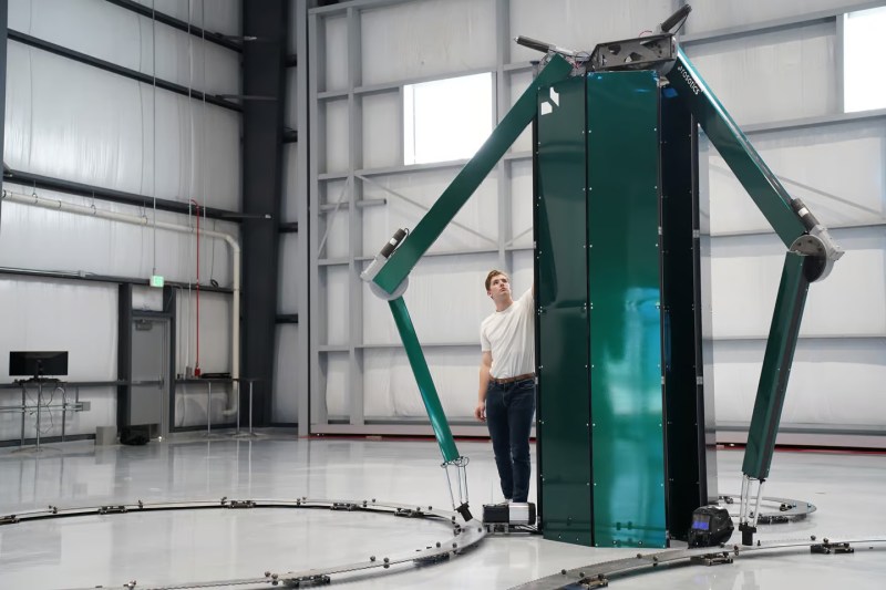
A company in Arizona called Rosotics has developed a large-scale printer based on this this method that they’re calling the Mantis. It uses three robotic arms to lay down metal prints of remarkable size, around eight meters wide and six meters tall. It can churn through about 50 kg of metal per hour, and can be run off of a standard 240 V outlet. The company is focusing on aerospace applications, with rendered rocket components that remind us of what Relativity Space is working on.
The induction heating method for the feedstock not only means they can avoid using power-hungry and complex lasers to sinter powdered metal, a material expensive in its own right, but they can use more common metal wire feedstock instead. In addition to being cheaper and easier to work with, wire is also safer. Rosotics points out that some materials used in traditional laser sintering, such as powdered titanium, are actually explosive.
Of course, the elephant in the room is that Relativity recently launched a 33 meter (110 foot) tall 3D printed rocket over the Kármán line — while Rosotics hasn’t even provided a picture of what a component printed with their technology looks like. Rather than being open about their position in the market, the quotes from CEO Christian LaRosa make it seem like he’s blissfully unaware his fledgling company is already on the back foot.
If you’ve got some rocket propellant tanks you’d like printed, the company says they’ll start taking orders in October. Though you’ll need to come up with a $95,000 deposit before they’ll start the work. If you’re looking for something a little more affordable, it’s possible to convert a MIG welder into a rudimentary metal 3D printer instead.


Something doesn’t quite add up about the claim it can run from a 240V outlet. They’re claiming that it runs up to 50kg of material per hour. Let’s say that it’s aluminium – heat capacity is 900 J/kg/K and latent heat of fusion is 400kJ/kg. Work all that out and the total energy required to heat 50kg of aluminium to its melting point of 660°C and then melt it is about 50MJ. If it does that per hour, then the average power requirement is 50MJ/3600s = 14kW. That’s a heck of a lot of power to draw from a “standard 240V outlet”.
It’s probably running off a standard 63A outlet. 14kW is naff all really.
Ah I see! I hadn’t appreciated that you could get outlets rated that high – the most I’ve dealt with are 32A.
So not for home use for sure. Industrial power outlet are rated higher for heavy machines.
Could also be 3 phase.
The original article states 240V “industrial”, and it´s exactly that: 3 phases 240V and 25 or 32A or more. So, not a 10kV beefy power line, but something that anybody can have at home.
Unfortunately, the ape assembling this piece of text lost that important detail. That´s what happens when one makes a digest of an article without spending enough efforts to understand it, or just by ignorance. Unfortunately again, a good majority of the articles here have poor / imprecise wording.
You should ask for a refund.
Here in Finland household have normal 3x25A 240V, And sauna takes about 6kWh :)
Yes and that’s only if you have a perfect 100% efficient heating system. I can tell you that it’s not the case even with induction. So, it’s very likely their claims are just renderware.
There’s 50amp 240v plugs for residential use, electric cars love them.
And it could be 240v 3 phase, still a “standard outlet” in an industrial setting. 75amp is common, and I’ve seen 100, 150, and 200amps in marine settings, though they usually step up to 460v when things are that power hungry to save on wire size.
Really power hungry stuff can dip into 4kv and higher, vut I’ve never seen that on a plug.
If their goal is to use wire feed, then they’d need to actually describe why all this larking about with induction heating is actually desirable, vs. the arc-based deposition Relativity – among others – have already proven to be viable (as well as every wire feed welding process).
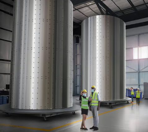
The combination of absolutely no output shown, absolutely no functioning mechanism shown, and vague renderings of randomly riveted tubes (why do you need to rivet it if you’re additively manufacturing it?) makes this seem like pure productless investor-bait.
It does seem like they’re trying to reinvent the MIG welder. I’d certainly want to see a tank they’d made before they got a deposit (or an investment) from me.
There’s a welding helmet in the photo above, so an arc is being used somehow. Maybe the induction coil just pre-heats the wire to give the arc less work to do, or it inductively heats the target area before more metal gets deposited ¯\_(ツ)_/¯
Or, as you say, maybe it’s pure bolognium.
I think you´re on the right track. Also controlling the cooling rate of the metal is quite crucial to get more even layers. I´d bet that thing looks like a MIG welder with some induction coil(s) around.
Well the rivets are to hold on the strengthening braces that are visible on the cylinder to the right that Bryan cropped off because it was even worse of a photoshop attempt. At least it looks like they used their warehouse as the background so founded in some reality?
Even if they don’t explain why it’s better than arc-based, they should at least acknowledge that it exists rather than only harping on about lasers!
“It’s a very natural way of 3D printing a metal, in my opinion,” – sure, that’s why even hobbyists have demonstrated alternatives. – personally a more natural way of 3D printing I would have gone for (if MIG/MAG style arc welding isn’t good enough is to use a TIG arc approach and have a constant arc heat the metal and feed a wire in separately (feeds+speeds are more of a challenge but I’m sure a bit of computer vision could watch a puddle)
If you weren’t sure this company was an investor cash grab, take a look at rosotics.com/press. This page is not linked from their main page, but contains some downright laughable posts, like their “Crawler” – a spider drone using lasers, or “Stinger” their aerial drone based AM system. The fanciful claims and buzzwords are clearly meant to dazzle investors who are ignorant when it comes to engineering. Everything they do they claim as boundary breaking or revolutionary!
“Well the rivets are to hold on the strengthening braces that are visible on the cylinder to the right that Bryan cropped off because it was even worse of a photoshop attempt. ”
The entire point of using additive manufacture for a braced tank is to build the bracing into the skin rather than traditional skin + hoop/stringer construction or pilled isogrid/orthogrid. If you have to print a bunch of separate components and then weld them manually, all you’re doing is adding cost and increasing production time.
s/pilled/milled
Hmm but when we have induction heating we can go to certain point and then it stops (building temperature stops at curie temperature) So how those this work? 5 yers ago on internet there was metal 3dprinter with sintering process .. so this why is this hype ?
It doesn’t have to stop at the curie point. The fact that they’re induction heating aluminium should be a clue to that! Serious power induction heaters work via induced current and don’t rely on the material being magnetic.
Just an example of poor writing; nothing remains magnetic near its melting point anyway, it has to be by eddy currents.
Even the author of the NewAtlas article threw a bit of shade on them for not having any example results – plus this zinger of a caption to their group shot “Christian LaRosa, center, with members of the Rosotics team, looking like they’ve just dropped a banger of a record” :-)
As an idea, it sounds quite interesting – effectively push metal wire to a soft/plastic point so it can adhere to itself (just like a filament 3d printer) – it’s just a shame that there’s little evidence and instead lots of sound bites (“I’m an engineer by education, by training and by practice,” he says, “I’m a founder by necessity – the necessity to overcome this limitation in 3D printing. When it became apparent that this process could to that, I couldn’t sleep at night until it existed.”) :-/
Oh, also looking at the machine platform – I hadn’t appreciated that they actually rotate the base (looks like a massive cog on some sort of low-friction wheels?)
https://www.youtube.com/watch?v=3-_2FXQH4co
say it with me….VAPORWARE!
This company had two previous iterations, the “Crawler” hexapod mounted printer and drone based “Stinger.” There aren’t any example prints or demonstrations of those either, just more soundbites. https://www.rosotics.com/post/this-was-crawler-our-initial-prototype
https://www.rosotics.com/post/stinger-and-rapid-induction-printing-a-new-way-to-create
I bet it can’t print copper or silver :-)
Looking at the images there are high torque motors at the base of each of the arms that will spin the three cylinder on some type of lazy susan ring that are being “printed” on top off.
So this thing can either print three cylinders or three domes, or three cylinders with one dome endcap in it’s current configuration and that is all ? Or am I missing something ?
i was thinking exactly the same but the whole machine seems wonky to me i doubt you can even reach the center / make a dome with it. it seems to be suffering from a bad case of “neofordisme”: you can have any shape your want as long as its a cyclinder of X diameter.
in all seriousness though am i the only one getting an uncanny valley kinda vibe from that printer picture? something seems just off to me.
“we’re no kids here you know”
To paraphrase, on the internet no one knows you’re a young goat.
It just seems like it’s going to be really, Really, REALLY hard to get any good metallurgy in the final part. It’s basically 100% weld seam, with all of the grain structure of cast metal.
Typically, metals that are intended for high-stress use are rolled or forged in tandem with precise tempering and heat treatment control in order to develop a very specific grain and crystalline structure to produce light, tough, homogeneous, predictable, characteristics. This stuff.. not so much.
While I’m not saying welds can’t be durable and strong, there’s still a reason they are very carefully inspected.
Looking at the pictures, I don’t think those are working prototypes. To the lay person they look convincing, but to a welder, they will ask “where’s the beef?”.
The end effector looks way too dainty to be anything around a welding setup. The ring and drive are not connected to the base or floor (you need things to stay in relative position to one another). The whole apparatus looks like maybe 10k in steel and various surplus parts.
To me this looks like one of those mockup kickstarters intended to defraud people of their money.
Yeah, really? You can see by their face’s it is VAPORWARE 😂
April is a couple day’s from now, too early posted 😹
In the source article they say they can melt non-magnetic materials by inductively heating a ferrous nozzle and then using that nozzle to heat the non-magnetic wire (like aluminum). So it’s essentially exactly the same as regular plastic 3D printers with a hot nozzle that melts the filament.
So they are heating say a steel/iron nozzle up to near it’s curie point 770°C (1043K; 1418°F) and then using it to melt Aluminium at 660.32°C (933.47K;1220.58°F). Smart.
Could be another uBeam style idea, time will tell https://hackaday.com/2015/10/20/the-curious-case-of-ultrasonic-power-transfer/
The founder seems to be power-posing in photos a lot, surely another bad sign 🤔