
When [Jay Bowles] demoed his first-generation ion thruster on Plasma Channel, the resulting video picked up millions of views and got hobbyists and professionals alike talking. While ionic lifters are nothing new, this robust multi-stage thruster looked (and sounded) more like a miniature jet engine than anything that had come before it. Optimizations would need to be made if there was even a chance to put the high-voltage powerplant to use, but [Jay] was clearly onto something.
Fast forward six months, and he’s back with his Mark II thruster. It operates under the same core principles as the earlier build, but swaps out the open-frame design and acrylic construction for a rigid 3D printed structure designed to more effectively channel incoming air. The end result is a thruster that’s smaller and has a lower mass, while at the same time boasting nearly double the exhaust velocity of its predecessor.
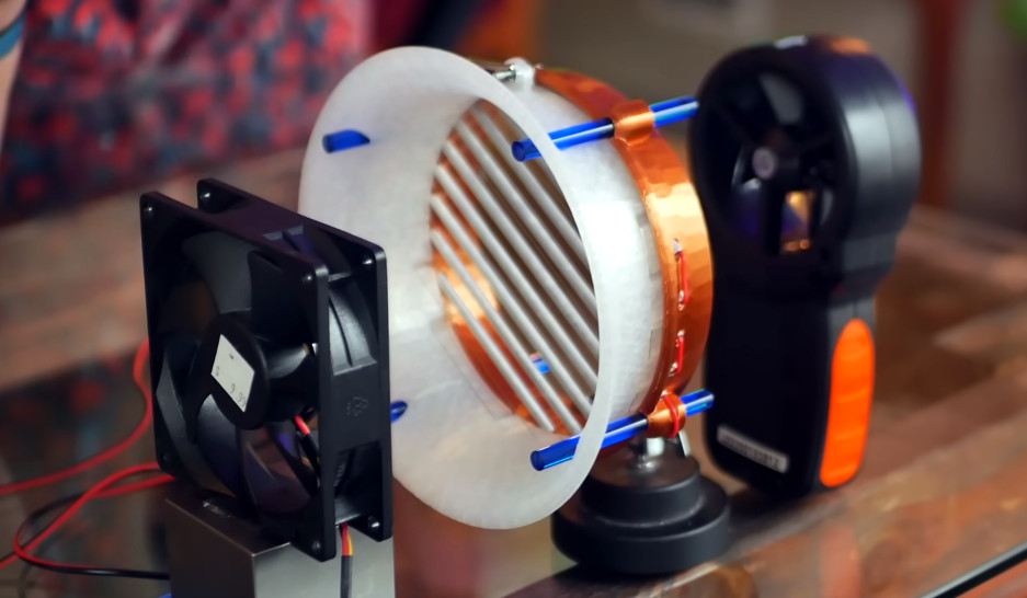
Even though many lessons were learned during the design and construction of the original thruster, [Jay] still built some variability into this version so he could experiment with different configurations. The electrode spacing can be adjusted by sliding the 3D printed sections back and forth along the blue acrylic rods, and they can also be rotated in relation to each other.
This allowed him to determine the best spacing, and test out a popular theory put forth in the comments of the previous video — the idea that that rotating the electrodes 90° from each other would allow for more predictable (and therefore more rapid) air flow. Turns out this actually reduced the air velocity through the thruster, so he quickly switched back to the original configuration.
Tests on a single stage of the thruster were very promising, but when [Jay] combined three of them together, the end result was a bit lackluster. He tripled the mass and length of the thruster, but only got a slight bump in air velocity. After talking to [Alex Whittemore], long-time friend of Hackaday and legit rocket engineer, the duo came up with an interesting test — if you use a fan to force more air into the throat of one section of the thruster, do you get a corresponding increase in velocity on the output side? The answer was no, indicating that not only was airflow being restricted, but that the additional thruster stages weren’t really being utilized.

From these tests, [Jay] switched the positive electrodes to a thinner gauge wire, and replaced the tubular brass ground electrodes with lighter rods that have a wing-like aerodynamic shape. In this final configuration, the thruster was capable of accelerating incoming air to 4+ meters per second while consuming 90 watts.
The unit’s final mass of 450 grams represents a 10% reduction from the first generation thruster, but even with the improved performance, it’s still going to take more work before [Jay] can realize his dream of propelling a winged aircraft of his own design with high-voltage. Whether or not it manages to slip the surly bonds of Earth, we’re looking forward to seeing the next generation of this fascinating project.


No mention of actual thrust in this write-up, but if that’s about 12 cm diameter, and assuming uniform velocity across the bore, it’s moving about 40 liters of air per second. At 1.2 grams per liter that’s 0.2 newtons! And a power in the air stream of 0.4 watts. So, 0.4% efficient. Good start!
Alternative metric is watt per newton, which is 450 watts per newton, not shabby. For reference, the GE9X jet engine comes in at roughly 200 W/N (yes, a 777 at takeoff really does have a pair of 100 megawatt power plants on its wings)
100 megawatts per wing… having a hard time wrapping my head around those numbers in that context. I see jet engine and immediately think “thrust” not watts.
So, knowing what he does about geometry and surface area of his electrodes is Bowles just looking at economy of scale on this? How close are we to a mini-max equation on the theory?
More importantly what do the Reynolds numbers look like inside of the thruster and on the electrodes? Assuming we ever get stellerators down to the size of a big block V8 we might very well see plasma based atmospheric engines.
Almost half as good as a commercial mass transportation jet engine is not shabby indeed! I’d bet you six Quatloos that commercial, profit-making air travel has been done on engines with a worse rating!
Hopefully Jay will look into putting together some kind of thrust measuring stand as the project goes forward, as it would be good to have some solid numbers.
What happened to good old thrust/weight ratio?
No engine goes anywhere without that one
and for 100MW output the compressor use about 200MW
Yes, the 100 MW is net. The power recirculated inside is much more, and the exhaust turbines handle it all: about a third of a gigawatt. The power density is crazy.
A 777 has the same power:weight ratio as a top fuel dragster, but its engines weigh a third as much (as a fraction of vehicle weight), run at higher RPM, and for thousands of times longer.
Need to get this guy working in the water as well as the air. Nuclear subs have all the megawatts you’d ever want and lack of moving parts is a huge plus. And maybe you’d eventually figure out something to get closer to electric cargo ships. Maybe.
Well if it’s a nuclear sub, you want the heat exchange from the pile to expand sea water, combined with a Tesla valve layout to ensure the warm water gets pushed out the back.
Sean Connery knew that!
Ease of tracking that propulsion makes this only viable in commercial settings though…
We already had electric cargo ships. ns savannah and otto something. Old school so no containers.
You should expect a move away from diesel in the very near future. More and more ships are ammonia powered. No one wants to sail on a mega bomb, so storing hydrogen isn’t an option. At work we are converting ships over from diesel electric to ammonia electric. It converts ammonia on fly to hydrogen, so you avoid having to store hydrogen with all the problems that has. You can travel huge distances with heavy loads. Only has nitrogen and water fumes coming out of the exhaust. It’s amazing.
MHD propelled ships are a been-and-gone tech (e.g. Yamato-1), but used a different mechanism of action.
The problem with using a ‘lifter’ type arrangement in water specifically is water is conductive, and lifters rely on a nonconducting neutral medium to work in (strip electrons from molecules on entry, accelerate the ions, neutralise on exit, with the ions whacking into neutral molecules in between to actually produce the net thrust).
Hunt for Red October? https://en.wikipedia.org/wiki/Magnetohydrodynamic_drive I think is what we’re looking for. I’m sure calculations have been done if you ‘dive’ in… yes, its proven tech. I’m sure in the 30 years since the navy might have looked at it a few times in the past :D
If multiple stages in series aren’t increasing airflow, what if they are in parallel?
You combine airflows with a variation on car exhaust piping.
Yep, I think it’s fake.
Interesting but how does this compare to an electric motor and propeller in overall efficiency for propelling a plane as a reference for us who are engineering deficient.
Your areodynamic tubes aren’t so areodynamic. You need flat or very oblong shaped tubes. The best thing would be to use flat metal ribbon for the ground electrodes (wny use tubes). This will reduce the drag over the electrode. Also the thin wire is correct, but the other ground electrode is typically far wider than the wire. The thickness of the ground electrode should be as thin as the 36 gauge wire. However the width should be far wider than the 36 gauge wire. It would be interesting to find out what the best ratio for the widths should be. The hot wire being round and small. How wide should the ground electrode be to provide the best ionization, but not add too much drag. One final thing. What about the optomal spacing between thruster segments? Could that be adjusted to get better performance? THe spacing between the electrodes might need to be made farther appart depending on the velocity of the inlet. So, downstream segments won’t accelerate as much unless their electrode spacing is made just a bit further appart.
Would increasing the number of positive and negative points be of any value? There’s got to be some point of no improvement, but the more actual propelling force devices within a single stage should have a positive effect on the amount of air moved.