Over the years, we’ve seen some modern microcontrollers turn out to be 5V-tolerant – now, RP2040 joins the crowd. Half a year ago, when we covered an ISA card based on a Pi Pico, [Eben Upton] left a comment saying that RP2040 is, technically, 5V tolerant for GPIO input purposes. The datasheets don’t state this because the reality of 5V tolerance isn’t the same as for natively 5V-tolerant chips – for instance, it doesn’t extend all the way to 5.5V for it to be ‘legally’ 5V-tolerant, as in, what 5V tolerance typically means when mentioned in a datasheet.
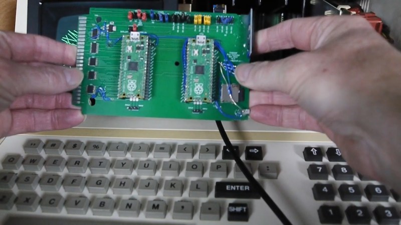
Having read that comment, [Andrew Menadue] has set out to test-drive the RP2040 GPIO capabilities, in a perfectly suited real-world scenario. He’s working with retro tech like Z80-era computers, using RP2040 boards for substituting entire RAM and ROM chips that have died in his FX9000P. Not only do the RP2040-driven replacements work wonders, using RP2040 boards also turns out to be way cheaper than sourcing replacements for chips long out of production!
Previously, [Andrew] used level shifter chips for interfacing the RP2040 with 5V systems, but he’s rebuilt a few designs of his without level shifters for the sake of this experiment. Now, he reports that, so far, those boards have been running long-term without problems. Together with [Eben]’s comment, this instills confidence in us when it comes to our RP2040 forays and 5V inputs.
There are a number of important caveats to this, that you should read up on. Some major points – certain GPIOs (like ADC ones) can’t take it, the GPIOs aren’t 5V-tolerant when set to output, and you shouldn’t feed the GPIOs 5V when the RP2040’s VDDIO is not powered up. [Andrew] points out one such case himself – one board of his has shed all level shifters except for the 8-bit address bus, which is driven by either the CPU or the RP2040 at different times, and that would result in 5V on an output-set GPIO when contention happens. All in all, if you’re working with 5V logic and your application is more hacking than business-critical stuff, you can shed the level shifters, too.
In the video, [Andrew] also shows some cool RP2040-based IC substitute boards – there’s followup videos on his channel and a GitHub repo if you’d like to learn more about them! All in all, this is a surprise, to be sure, but a welcome one, making quick Pi Pico hacks even quicker, and a few RP2040 projects even easier to build – for instance, who knows, maybe that Pico-powered ISA card can shed its CPLD. It’s nice when we get an under-the-table statement with a technical elaboration – otherwise, we might need to break out the curve tracer, like [Avian] did when confirming the ESP8266 5V tolerance.


I’m surprised they didn’t just make the GPIO 5 V tolerant. Some other microcontrollers like STM32 manage it. The rp2040 is meant for hobbyists and a lot of hobbyists level components still use 5 V.
It’s not a simple switch you flip in the design software to enable it, it’s something that costs extra in design time and chip area, and interacts in myriad ways with the performance of the GPIOs. The RP2040 was a deliberate attempt to do things differently to existing products in the market; if you want what those other products do then get them instead.
And I say that as someone who is directly impacted by this specific issue. I can grumble about it, but I’m not going to say they were wrong or that they should have specially catered to my niche use cases.
I’m happy to have some confirmation that I can get away with a direct connection in limited circumstances though!
Even STM32 isn’t 5V tolerant when VDD is off or if the GPIO pin is in analog mode, so there are caveats that may require external buffers.
An easy way to handle this is often to use series resistors to limit the current through the ESD diodes to 1 or 2mA
A series resistor will in combination the GPIO capacitance slow down the slew rate making pin change slower.
it’s not about ESD diodes here specifically, and, check the “caveats” link – it describes that series resistors aren’t a good protection for this specific situation.
In modern processes making a 5V tolerant IO is not so simple, and might even not be possible. At least if the process isn’t quantified for 5V io you would have to do that yourself, which takes a lot of time.
No matter what anyone posted somewhere random on the internet says, and what some quick tests show. The documentation of the RP2040 chip is pretty clear on this. It’s not 5V input tolerant and you most likely will damage the chip if you put 5V input on it. Very likely you are heating up the internal ESD protection diodes, causing some heavy reduction in lifetime of the chip.
The datasheet, chapter 5.5.3.1 clearly states that the absolute maximum on an input pin is IOVDD + 0.5v.
IOVDD is usually at 3.3V, so that 3.8V. Very long way off from 5V.
Other then that single post on HaD (which you cannot verify if it’s authentic) nothing else seem to state from the Pi organization that this 5V is acceptable. Every other source says “don’t do this”.
Tell me that you didn’t read the links without telling me you didn’t read the links.
yeah what the hell. unironically – it must’ve taken some time to type out that comment, and that time would’ve been much better spent clicking on the multiple inline links I provided for this exact purpose.
The data sheet tells you what is promised to be safe.
It’s not rated for 5V, meaning there no guaranteed that 5V will never damage it. That is, 5V could damage it in some cases. Like when 5V isn’t 5 volts, but 5.4 volts.
Which is different from “you most likely will damage the chip if you put 5V input on it”. We know that people put 5V on it all the time without damaging it. And maybe sometimes it does cause damage. Most likely, it won’t – but it might.
So it’s a risk assessment situation. How bad is it if you damage a Pico?
If my Pico was running a cubesat, having it blow could waste a $20,000 launch. I wouldn’t put 5V to an input of it’s on a cubesat.
On the other hand, for little projects at home like my logic analyzer, the risk analysis is very different. At $5 each, I pick up a couple Picos every time I swing by Microcenter. I have several in my drawer. If I blow an input on one, oh well. Replacing it costs less than my lunch, and I already have a spare right there in the drawer.
Even if it works in this case. It seems to me to be bad design to do it. There are good reasons (many of which noted in this article) to not do that.
there’s no universal ‘bad design’, all of it heavily depends on what you’re building. I also note a few scenarios where this 5V tolerance is strongly beneficial, mind you!
That’s cool and good to know in a pinch but for the cost of a couple resistors one can be more confident that neither situation nor batch quality, reasonable signal variance nor long term use will cause a problem.
check the video – Andrew demonstrates a small board where there’s just no board space to add anything of the sort.
from the RP2040 data sheet:
5.2.3.1. Absolute Maximum Ratings define IOVDD (I.O supply voltage) as -0.53V to 3.63V
Voltage at IO = Vpin is given as IOVDD +0.5V = 4.13V
Hence 5V is way out of spec!
Well, might work (on some batches maybe), and will for sure lead to bigger numbers of RP2040 sold (when people let loose on magic white smoke) ..
Everything can be 5V tolerant, for a while.
I will use it as spec’d. But as cheap as the little board is and you ‘need’ a fast 5V input for some reason. go for it. It’s only a PCB board with some parts on it anyway. Only out a couple bucks if it lets out the white smoke. Big deal. Pull another from your large stash and go forward, lesson learned.
5V tolerance wasnt such a big deal pre big chip shortage when SN74LVC16245 were $0.1 (barely above cost of packaging), but now all of a sudden SN74LVC16245 ran out and SN74LVC16T245 are >$1
Ignoring formal specs is what hacking is all about. There could have been better ways to do this, but Iit is certainly an interesting exercise, and toasting a $4 dev board during a hobby project is not a big issue.
I thought 5v logic went out back in the 90’s. At least that is when I quit using it. People better get with the times. 5V logic is old school and out of date. It is so 74XX TTL.
Did you happen to notice he’s interfacing with a 1981 computer?
In 2063, folks will be asking you why you care about your retro 2023 stuff.
Sometimes old bus standards keep you using it. If you need 5V logic for can, you need a 5v regulator.
If you chose additionally 3.3V as system voltage, it will cost you additionally that regulator as well.
That’s why there still are compatible controllers. Even smaller controllers with 2 separate power rails for gpios! The avr64db series has it for example.
I’m wanting to use an I2C LCD display, which needs to be powered with 5V and has pull-up resistors to 5V on the SDA and SCL. Would this be one of those instances where I’d be safe to leave those pull-ups in place?
If the RP2040 is configured as an output then it isn’t 5V tolerant. So, as you are using it as and output to drive SDA and SCL, it’s quite likely that you will have 5V on the pin at least for a short time, so in this case you’d need some sort of level shifter or other protection for the RP2040 GPIOs.
So, no, not safe to have pull-ups.
Just to do a 2025 comment…
RP2350 is finaly 5.5V tolerant