No Home Cinema Is Complete Without A Motorized Projector

In the home of the future, everything is automated. Some of us are already there, in dwellings fully tricked-out with IoT and smart home devices. But they don’t somehow look as futuristic as a home in which everything is motorized. We don’t know whether this was the intention, but we certainly get a futuristic vibe from [Sam Baker]’s home cinema projector mount. It’s no mere bracket, instead on command the projector descends from concealment in the ceiling on a custom scissor lift mechanism.

A scissor lift is a simple enough mechanism, but since he was 3D printing one that had to withstand the weight of the projector, it took him a while to get it right. Even the lead screw which drives it is also printed, turned by a stepper motor. As the brains of the unit needn’t be particularly accomplished, an Arduino Nano does the job well enough.

It’s fair to say that his projector isn’t the heaviest of models, but the result glides smoothly down from the ceiling for a perfect home cinema experience. We like it.

Opening Up ASIC Design

The odds are that if you’ve heard about application-specific integrated circuits (ASICs) at all, it’s in the context of cryptocurrency mining. For some currencies, the only way to efficiently mine them anymore is to build computers so single-purposed they can’t do anything else. But an ASIC is a handy tool to develop for plenty of embedded applications where efficiency is a key design goal. Building integrated circuits isn’t particularly straightforward or open, though, so you’ll need some tools to develop them such as OpenRAM.

Designing the working memory of a purpose-built computing system is a surprisingly complex task which OpenRAM seeks to demystify a bit. Built in Python, it can help a designer handle routing models, power modeling, timing, and plenty of other considerations when building static RAM modules within integrated circuits. Other tools for taking care of this step of IC design are proprietary, so this is one step on the way to a completely open toolchain that anyone can use to start building their own ASIC.

This tool is relatively new and while we mentioned it briefly in an article back in February, it’s worth taking a look at for anyone who needs more than something like an FPGA might offer and who also wants to use an open-source tool. Be sure to take a look at the project’s GitHub page for more detailed information as well. There are open-source toolchains if you plan on sticking with your FPGA of choice, though.

One of the PCB projects involved being held in the author's hands - a large-ish green board, with two Pi Picos visible on it

RP2040 And 5V Logic – Best Friends? This FX9000P Confirms!

Over the years, we’ve seen some modern microcontrollers turn out to be 5V-tolerant – now, RP2040 joins the crowd. Half a year ago, when we covered an ISA card based on a Pi Pico, [Eben Upton] left a comment saying that RP2040 is, technically, 5V tolerant for GPIO input purposes. The datasheets don’t state this because the reality of 5V tolerance isn’t the same as for natively 5V-tolerant chips – for instance, it doesn’t extend all the way to 5.5V for it to be ‘legally’ 5V-tolerant, as in, what 5V tolerance typically means when mentioned in a datasheet.

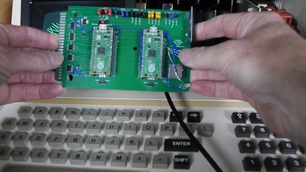
Having read that comment, [Andrew Menadue] has set out to test-drive the RP2040 GPIO capabilities, in a perfectly suited real-world scenario. He’s working with retro tech like Z80-era computers, using RP2040 boards for substituting entire RAM and ROM chips that have died in his FX9000P. Not only do the RP2040-driven replacements work wonders, using RP2040 boards also turns out to be way cheaper than sourcing replacements for chips long out of production!

Previously, [Andrew] used level shifter chips for interfacing the RP2040 with 5V systems, but he’s rebuilt a few designs of his without level shifters for the sake of this experiment. Now, he reports that, so far, those boards have been running long-term without problems. Together with [Eben]’s comment, this instills confidence in us when it comes to our RP2040 forays and 5V inputs.

There are a number of important caveats to this, that you should read up on. Some major points – certain GPIOs (like ADC ones) can’t take it, the GPIOs aren’t 5V-tolerant when set to output, and you shouldn’t feed the GPIOs 5V when the RP2040’s VDDIO is not powered up. [Andrew] points out one such case himself – one board of his has shed all level shifters except for the 8-bit address bus, which is driven by either the CPU or the RP2040 at different times, and that would result in 5V on an output-set GPIO when contention happens. All in all, if you’re working with 5V logic and your application is more hacking than business-critical stuff, you can shed the level shifters, too.

Continue reading “RP2040 And 5V Logic – Best Friends? This FX9000P Confirms!”

A Soft Soldering Jig For Hard Projects

We’ve seen some absolutely gorgeous freeform circuit sculptures. There’s a mystic quality to taking what has normally been hidden away for safety and reliability reasons and putting it on display for everyone to see. Of course, creating these unique circuit sculptures takes considerable time and effort. [Inne] created several silicone soldering jigs to help with these tricky joints.

While a vice or helping hands is crucial for many joints, when dealing with tiny SMD components and exacting angles, you need something a little more specialized. Double-sided tape is often recommended, but heat ruins the adhesive and SMD components like to stick to soldering iron tips. Since silicone tends to be heat resistant, it makes a decent material for soldering on. [Inne] uses a city analogy with the cups for soldering called plazas, each with a hole (called a manhole) leading to a foot-switch vacuum pump to keep parts in place. The OpenSCAD code is available on GitHub under a GPLv3 license. It generates a two-part mold that you can cast in A-8/A-15 silicone.

It’s a clever project that makes it far easier to assemble gorgeous circuit sculptures. We love the design and thought that went into it, particularly the naming scheme as we often find appropriately naming variables in OpenSCAD quickly becomes difficult.

A white, house-shaped clock with the words "TEMPUS NECTIT" written in faux Roman script in black on a strip of silver at the base of the "roof." a white power cord extends from the left of the enclosure, and the center of the clock is a 22 pin knitting machine wheel with one pin covered in silver metalic. A white plastic peg extends from the bottom right of the enclosure to hold the feedstock yarn.

Tempus Nectit, A DIY Knitting Clock With Instructions

We’re no strangers to unusual clocks here at Hackaday, and some of our favorites make time a little more tangible like [Kyle Rankin]’s knitting clock.

Inspired by our coverage of [Siren Elise Wilhelmsen]’s knitting clock, [Rankin] decided to build one of his own. Since details on the build from the original artist were sparse, he had to reverse engineer how the device worked. He identified that a knitting clock is essentially a knitting machine with a stepper motor replacing the hand crank.

Using a Raspberry Pi with an Adafruit motor hat connected to a stepper motor and a 3D printed motor adapter, [Rankin] was able to drive the knitting machine to do a complete round of knitting every twelve hours. By marking one of the knitting pegs as an hour hand, the clock works as a traditional clock in addition to its year-long knitting task. [Rankin] says he still has some fine tuning to work on, but that he’s happy to have had the chance to combine so many of his interests into a single project.

If you’re looking for more knitting hacks, check out this knitted keyboard instrument or a knitted circuit board.

Continue reading “Tempus Nectit, A DIY Knitting Clock With Instructions”

Retrotechtacular: Solder Like Its 1944!

When we first saw this 1944 US Office of Education film about hand soldering, we figured it might still have some good information. Well, perhaps it does, but the 1944 soldering was with a giant iron, and the work looked more like metal bricks than anything we’ve soldered lately. Of course, the physics is all the same, but some of the terminology, like “sweating in” isn’t anything we’ve heard before, although we have heard of sweat soldering.

They do show some electronic soldering on components, including some interesting-looking coils. But the irons look more like a bad science fiction movie’s idea of a lightsaber. The solder is equally huge, of course.

Continue reading “Retrotechtacular: Solder Like Its 1944!”

Typewriter Mashup Becomes 120-Year-Old Teletype

Vintage typewriters can be beautiful and elegant devices. But there’s a limit to their value if, as with the 1903 Remington owned by [Daniel Ross], they are fire-damaged and have a seized mechanism. What did he do with what was essentially a piece of scrap metal? Produce an unholy mashup of the vintage machine and a 1988 Sharp daisy wheel typewriter to make a steampunk-style teletype, of course!

Stripping down both machines was evidently no easy task, and the result he’s achieved has the Sharp’s printer mechanism at 90 degrees to its original orientation sitting below the roller in the space once occupied by the Remington’s type bars. We’re sad to see that the keyboard on the older machine appears to be inoperable, but on the other hand each letter does light up as it’s typed.

Meanwhile at the electronics side the components from the Sharp have been transferred to a custom PCB, and the whole can be driven from a 300-baud serial line. As can be seen from the video below the break, the result is an unholy love-child of two typewriters that could scarcely be more different, but somehow it works to make an impressive whole.

If this project looks a little familiar to Hackaday readers, it’s because we’ve mentioned it in passing before. It’s hooked up to his COSMAC Elf retrocomputer, and we saw it in passing a couple of years ago at a much earlier stage of construction before the custom PCB and light-up keyboard.

Continue reading “Typewriter Mashup Becomes 120-Year-Old Teletype”