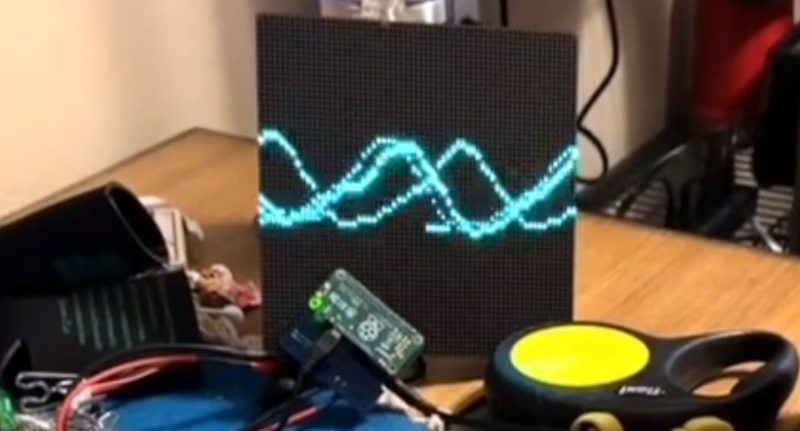
If you have a Raspberry Pi connected to an LED matrix, you might think about creating a simple oscilloscope. Of course, the Pi isn’t really well-suited for that and neither is an LED matrix, so [Thomas McDonald] decided to create the OhSillyScope, instead.
The device isn’t very practical, but it does add some flash to live music performances or it makes a cool music visualizer. The matrix is only 64×64 so you can’t really expect it to match a proper scope. Besides that, it pulls its data from the Pi’s ALSA sound system.
You can find a video of the device on [Thomas’] Reddit post and a few additional videos on his Instagram account. Looks like a fun project and it also serves as a nice example if you need to read data from the sound card or drive that particular LED matrix.
We might have opted for PortAudio if we had written the same code, but only because it is more portable, which probably doesn’t matter here. Of course, you could also use GNURadio and some Python to drive the display. As usual, plenty of ways to solve any given problem.


I wonder if the raspi could do a realtime audio waterfall spectrum display with an RGB LED panel?
I have the parts, but my programming skills are limited to solder….
I don’t see why not. You could keep the FFT window size pretty small given the low resolution on the display.
You could do that on a 66MHz 80486 back in the 1990s. At the company I worked for back then, we had Toshiba “laptop” with a VGA resolution LCD built in. It could (and did) easily do a waterfall display of an FFT. That was the reason we had that computer at all. We used it for testing the audio frequency response of radio transmitters and receivers.
The bottle neck wouldn’t be the Pi. It’d be the communications protocol of the LED panel.
IIRC these matrices are just a bunch of shift registers to set column data and a row multiplexer so the controller has to manually multiplex the scanning of the LEDs one row at a time. I’ve seen people implement pretty high speed modulation to achieve higher color gamut at 60fps with fpga’s so I don’t think the communication interface will particularly be an issue. Keep in mind these types of displays are what is used to make video walls for commercial advertising applications.
How about an X-Y display that would visualize the separation of stereo signals? Back in the day, McIntosh receivers had one.
I’m doing a waveform plot on an I5 in realtime no problem. The RP can probably do that too. Just hook up a LCD monitor, and try to plot to a client window.