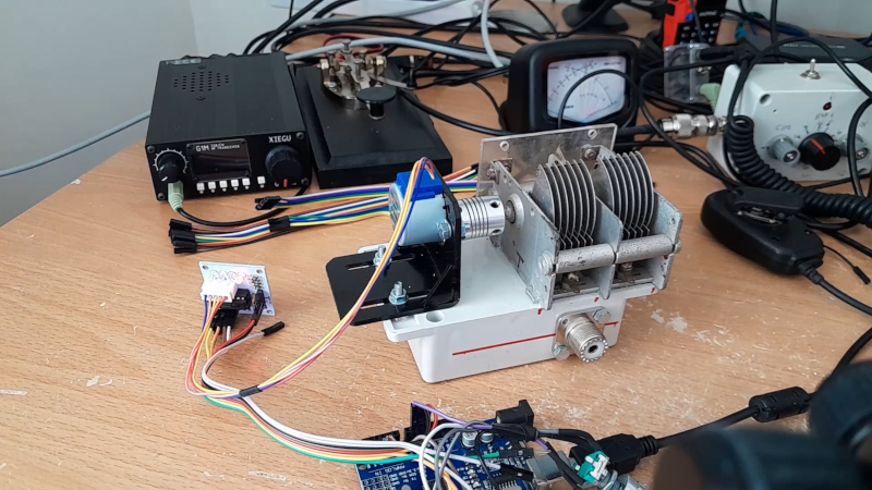
Magnetic loop antennas are great if you are limited on space since they are just a potentially small loop of wire. The problem is, they are sharply tuned. You normally have an adjustment capacitor to tune the antenna to different frequencies. [TekMakerUK] built one with a motor and an Arduino that he can tune from an Android phone. You can see more about the project in the video below.
If you want to transmit, the capacitor is often the weak part of the system. Luckily, some old gear yielded a capacitor with multiple sections and enough plate distance to handle the 5W desired. Of course, motor driving a capacitor isn’t a new idea, but this setup is nice since it uses a stepper motor and a rotary encoder.
For now, the control just moves the stepper to a particular position, but long term, there are plans to have presets for each band that the Arduino can set from a single command. You might wonder how the stepper knows where it is since there are no limit switches. It turns out he just stalls the motor and assumes it is at the far limit and then moves it to the other limit (see initMotor) in the GitHub source code.
Loops are easy to hide. This isn’t, of course, the first remote loop antenna we’ve covered.


What people don’t always realize is that magnetic loops are about 5% efficient.
Michelle Pacquette does a great talk about them, but it doesn’t appear to be archived.
Even though it’s 5% efficient, you can make world-spanning contacts sometimes.
I’ll have to check on that, not sure how you figure all of them are only 5% efficient.
I built one recently, it’s done a decent job of handling the less than ideal band conditions on 10m (designed for) and 15m (works, but less efficient).
It’s functional at 20m, but then I am approaching the lower end of the efficiency scale.
I’ve made contacts with in from Winnipeg to Europe, South America, and currently trying to find some stability in the ionosphere for Japan and Australia.
I’m transmitting with less than 10 watts.
The magnetic loop calculator I used estimated the optimum efficiency percentage (disregarding my build quality), as 84% on 10m.
Mag loops can be way more then 5% efficient it all depends on the loop circumference vs your target frequency.
They might be inefficient, but most people who use one, don’t have space for a real efficient antenna.
Eh, usually the problem on lower bands is not being able to cover a given band at all. 5% can be a success, even if it should be better.
I’ve worked stations on antennas that are 0% efficient – dummy loads! It is incredible – especially on the high HF bands (12m,10m, 6m) — how sensitive receivers are and how little the ionosphere/ground attenuate signals as the bounce around.
kindly submit your evidence that magloops are only 5% efficient. I am keen to study it. Mine are between 80%-95% efficient with over 345 QSO’s logged to prove it
Mike de ZL4MBW
Here’s one attempt at the math: https://wiki.eecs.yorku.ca/lab/emil/_media/technotes:loopantcalcs1.pdf
He is able to achieve much higher efficiencies than conventional hams, because his target frequencies are in the GHz and he can have a loop which is a half wavelength in size.
I imagine that the 80 to 95% efficiency you are quoting is getting a call back from the people you hear, rather than the efficiency of coupling your transmitted power to space-time. Magnetic loops are a compromise antenna that trades efficiency for size, in that the loop is usually a lot smaller than half a wave in circumference, and that is the main reason that the efficiency just can’t be very high. 80 to 95% would be the efficiency of a _theoretical_ full-size dipole in _free_space_, one with thick conductors, etc. Real dipoles aren’t in free space, so they have ground losses.
The other issue about small loop antennas is that they have really high voltages at the loop, and a lot of stored energy in the magnetic field. This means that the effect of resistance is multiplied, so you will see that commercial loop antennas sometimes have really thick conductors and the parts welded together to avoid resistance.
This doesn’t mean there’s any reason to feel bad about a small loop, just be aware that you’re essentially the same radiated power as a much lower powered transmitter connected to a good dipole or a quarter-wave vertical with a good radial field.
Efficiency depends on size. The loop calculators will quickly show that the (typical) 1-meter loop popular with builders has an efficiency of over 50% in the upper HF bands, while having efficiencies under 6% on 80 or 40 meters. It’s not valid to claim that all loops have 5% efficiencies, the efficiency is wavelength-dependent acriss the RF spectrum.
De WB2VUO
Keith 100% spot on. Bruce Perens tells me he has no idea what he is talking about. Probably never seen a real magloop nor used one either.
The circumference of the antenna is 10 feet, then, for a band (10m) where half a wave is 15 feet. That’s why it can be close to good, and will get progressively worse as that ratio increases. But consider that the radiation resistance isn’t going to be lower than the ohmic resistance unless it’s made out of hefty metal tubing with all of the parts welded together. And then add on ground losses, the field shape, etc.
I made a 2m(144MHz) mag loop that I tested in the carpark of where I used to work and got results of -3 to -6dB compared to a dipole. It was noticeably better than the helical on my 2m handheld. Suggesting much better than 5% “efficiency”.
de G0AFV
So, 50% of a theoretical dipole in free space. But at 2M you can have a practical antenna with a circumference of half a wave. This is not the case for lower frequencies.
For a parallel-plate open-air capacitor like this, how does one figure out how much RF power one can safely send through it?
Checkout this calculator:
https://www.66pacific.com/calculators/small-transmitting-loop-antenna-calculator.aspx
(meant to include it on my prior post).
For my antenna, 8.5″, with 3/8″ (0.375), at 28Mhz, 10 watts, it estimates a maximum voltage of 610.
(Note: change any of those parameters and it’s easy to get the voltage to jump to a few thousand.)
Short answer is probably not enough. Most of the available air gap capacitors you can find have fairly tight clearances and are mostly only good for receiving on.
Transmission usually involves the use of a vacuum tube butterfly capacitor as they are rated for high voltages, however another possibility is using an air-gapped capacitor. (google TA1LSX ).
These can be bought in pieces and basically designed for the voltage and capacitance you are interested (check out the online calculator at https://miguelvaca.github.io/vk3cpu/magloop.html for some idea of the relevant parameters vs frequencies, etc).
Since HV air-gap-caps are becoming harder to find and are expensive when they are found, I’ve seen nested, sliding metal tubes with a dielectric (PVC pipe?) between them used.
Also, I’ve wondered why no one I’ve seen has 3D printed air-gap-cap plates, covered them with copper or aluminum tape, and assemble them using readily available hardware like threaded rod.
There is an Air gap capacitor on thingiverse.com
Don’t use PVC. It’s a polar molecule and converts RF to heat. Teflon is non-polar, but more expensive than PVC. See https://www.appstate.edu/~clementsjs/journalarticles/zeus_dielectric.pdf
Well I only have a Xiegu G1M that is 5 watts so it should stand it, we’ll see!
There is a better calculator available online at https://miguelvaca.github.io/vk3cpu/magloop.html
This lets you put the details of the various materials you have access to in, and will give you its performance characteristics. You can adjust various values using the sliders and ‘design’ your loop accordingly.
I’d also strongly recommend checking out https://www.youtube.com/watch?v=2mwV-2urdF0 for some real world advice on how to build an antenna that meets expectations.
Like any antenna, the radiation efficiency of a magnetic loop antenna has many factors. A properly built mag loop can radiate nearly as well as a dipole. And in many real world cases the magnetic loop will have a superior radiation pattern to a sub optimal dipole. However a poorly constructed magnetic loop will often just be a leaky dummy load.
The secret is to minimise ohmic resistance at RF frequencies. This means large diameter tubing and minimizing joints. The “standard” octagonal loop design has twice as many joints as needed, if you solve Maxwells equations you will see that the area, not the shape is what is important. On a poorly constructed loop you will also often find braided cable connections to the capacitor. Braid is not the lowest loss choice at RF frequencies.
The energy you feed a magnetic loop with can only be dissipated as heat through resistance or as radiation. By going to great efforts to minimize ohmic loss the energy has no choice but to radiate. There are serious downsides with magnetic loops, such as the incredibly high Q of the antenna system. This often requires retuning with every frequency change. On low bands like 80 and 160 meters the bandwidth may not even be wide enough for SSB voice. Additionally the voltages and currents in a magnetic loop system can be spectacular and should be respected. The RF safe distance is something to consider when operating a magnetic loop in close proximity.
A.E. PhD
73
No choice but to radiate! I wish it were true. That is only the case if you consider heat to be radiation. Start with reading about radiation resistance, rather than ohmic resistance.
I use a mag loop here, Retired some years ago and moved into a senior housing which does not allow outside antennas, the Mag loop has allowed me to get on the air. with 2 watts I’ve worked 36 countries thus far in just causal operating. So they do work. But of course not like a good outside antenna.
Thanks for featuring and crediting my YouTube video, there is also a full article at http://www.tekmaker.co.uk/p/an-experimental-magnetic-loop-driven-by.html
As regards the efficiency this is one reason I used suck a long loop 5m, I ran the figures as you will see in the blog and here is a sample. I ran the figures for 40,20 and 15m. 20 m looks pretty good!
20m
Antenna efficiency: 71% (-1.5 dB below 100%)
Antenna bandwidth: 82.7 kHz
Tuning Capacitance: 44 pF
Capacitor voltage: 466 volts RMS
Resonant circulating current: 1.82 A
Radiation resistance: 0.535 ohms
Loss Resistance: 0.222 ohms
Inductance: 2.91 microhenrys
Inductive Reactance: 256 ohms
Quality Factor (Q): 169
Distributed capacity: 13 pF
Antenna “circumference”: 5 meters
Loop antenna Side length: 0.625 meters
Antenna diameter: 1.5 meters
Comments:
The specified conductor length of 5 meters is OK.
Conductor length should be between 2.60 and 5.20 meters at the specified frequency of 14 MHz.
As I keep stating, this is a starting point for my test bed, if it outperforms the YouLoop I will be delighted but it is of course, about the experimenting, I did watch a video that went into great detail of the design and efficiency calculations, here is a link https://youtu.be/ZmUQgyQ2uSg
Yes, most magnetic loops will have a much smaller circumference. But the brief math above is not considering the shape of the radiated field, and ground losses if it’s less than 60 feet high.