We like a project that makes us think, and that was certainly the case with [MS-BOSS]’s octave downshifter that’s an entry in our current op-amp contest. Instead of resorting to an FFT, or a PLL, it uses a technique best described as a custom analogue computer to implement the maths of octave downshifting. It’s an extremely clever approach, and we don’t mind admitting took us more than one read to understand how it works.
Just as you would with any mathematical problem, he’s split the job of halving the frequency into its constituent mathematical functions. The square root calculation circuit is probably the one that most required the dredging up of dimly-remembered analogue circuitry undergraduate courses for us.
The result is a fascinating read that’s well worth taking the time to understand if you have any interest in analogue electronics. It’s by no means the easiest way to make this particular effect in 2023, as we’re much more used to seeing our community make digital effects, but if you fancy yourself as any kind of op-amp designer, you really need to give it a look.


“well, there is one D-type register”
Naughty naughty!
Not only that, it’s used as an oscillator! At half the frequency!
Oooh, I’ve been a bad boy.
But yeah, it could have probably been implemented for example as a analog pulse counting circuit and two comparators, one to detect first rising edge and a second to reset the integrating pulse counter. Hmmm, might have to try that…
Am I overlooking the demo?
Hi, there’s a simulation of it so anyone can have a look how it works.
Though I surely can make some kind of recording of the device if simulation is not good enough proof for this contest (I personally believe that it’s much easier to tamper a physical demonstration than to tamper a simulation and go undetected).
And the bottom line which I am also stating in the documentation to make it clear – this device works properly only for sine waveform due to nonlinear functions involved.
I am trying to imagine what the harmonics will do to the output, especially the 90 degree phasing circuit. Retro sounding possibly?
Nasty things. Since there’s the square root, you will get more distortion / the harmonic content will change for sure.
And the synchronised inverter will probably stop being synchronised to the proper point on the waveform which will inevitably cause discontinuities in the signal, thus increasing the amount of distortion yet again.
If the harmonics were strong enough, they could even cause multiple triggers of the flip-flop during the cycle – another source of a lot of distortion.
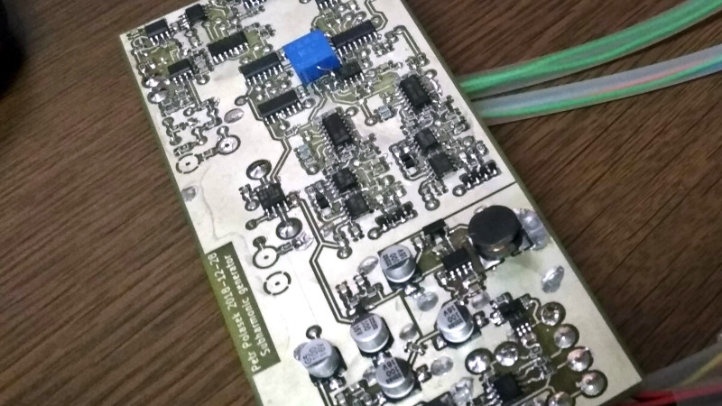
I’ve uploaded some photos from scope and a video of the thing. No audio yet because I have my stereo sound cardy thing in our makerspace where it’s used for streaming.
https://hackaday.io/project/190639-analog-oscilator-less-octave-down-effect-box/log/218263-a-demo-of-sorts-no-audio-in-video
Pretty darn cool
Ramzi Yousef most impressive op amp app by connection from Casio watch audio alarm to … ?
And then there was the dbx subharmonic synthesizer (aka Boom Box) – 1977 or 1978.
No micro in there!
That’s true but it uses just a divider to halve the frequency of input which results in a lot of harmonics (couldn’t find schematics, but that’s what people say on forums).
In fact, that’s just the first stage of my circuit :-)
Not quite.
It had 6 (8? I forget – it was a long time ago!) narrow bandpass filters whose outputs were pretty much sine waves. Then it changed the gain plus and minus on each zero crossing on each of these. That created a messy waveform that was then put through another bandpass (well, 6 filters). The output was then another set of sine waves that was summed into the output.
1/2 the frequency, tracked the amplitude automatically, and a volume knob to set the mix-in level.
It worked nicely.
I did the filters and helped with the rest of the design during my tenure at dbx.
Interesting. Is there some schematics available floating on the internet?
Wasn’t the original Rockman all analog? And designed by someone in the band Boston?
Hi, author here.
I probably forgot to mention the square root finding circuit calculates a logarithmic and exponential functions with 2:1 ratio of their slopes to get the square root.
My bad!