Even if surface-mount skills aren’t in your repertoire, chances are pretty good that most of us are at least familiar with SMD stencils. These paper-thin laser-cut steel sheets are a handy way to apply a schmear of solder paste to the pads of a PCB before component placement and reflowing. But are stencils good for anything else?
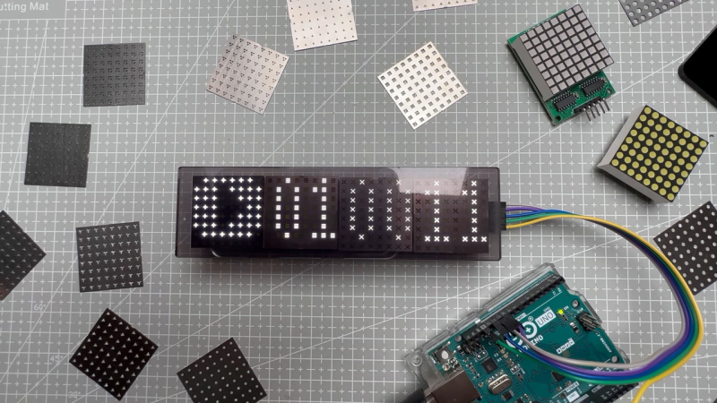
It turns out they are, if you’ve got some plain old 8×8 LED matrix displays you want to jazz up a bit. In this case, [upir]’s displays were of the square pixel type, but this trick would work just as well for a matrix with circular elements. Most of the video below is a master class in Adobe Illustrator, which [upir] used to generate the artwork for his stencils. There are a lot of great tips here that make creating one simple shape and copying it over the whole array with the proper spacing a lot easier. He also details panelizing multiple stencils, as well as the workflow from Illustrator to manufacturing.
When lined up properly over the face of the LED matrix, the stencils have quite an effect. We really liked the narrow vertical bars, which make the LED display look a bit like a VFD. And just because [upir] chose to use the same simple shape over all the LEDs in a matrix doesn’t mean that there aren’t other options. We can see how you might use the same technique to create different icons or even alphanumeric characters to create custom LED displays. The possibilities are pretty much limited to your imagination.
This isn’t the first time we’ve seen [upir] teaching old displays new tricks.


Stencil hacking! Brilliant – I never would have thought of that.
You win the Internet for the day.
Please check out my mask to convert LED matrix to 16 segment display.
https://www.youtube.com/watch?v=gt2merZcuno
that looks awesome.
Well that’s just about as sexy a solution as you could ask for. It’s got that 80’s era cyber-punk look to it too. Now I just need to find an application for it around the house.
Very impressive!
Fantastic use of lightpipes!
very cool
Adobe illustrator? Surely it’s two nested loops in Python, outputting some SVG, or DXF?
Uh huh.
Post your code to show us how easy that is, as compared to doing an array of objects in AI.
It really is. But the advantage is that you then don’t need a license for Adobe.
Really easy yet no sign of this code.
Once again, uh huh.
Meanwhile every graphic programs (licensed or not) has an array command. Even my laser control has it. But yeah, tell us more about this wonderfully short and easy to write code you imagined you can write.
“Why it’s only 2 lines of Python” sounds like the 555 of wannabe coders.
My point was why use something as complicated and expensive as Adobe Illustrator? The code itself is a trivial exercise for the reader. If you can’t do it then I suggest you read a book.
Wow, you’re a complete duck.
Hey look a stuck up rich kid who doesn’t know how to program
Considering how broad a range of applications have been found for the 555 et.al., I’m not sure that’s the insult you probably meant it to be. And actually, yes, a heck of a lot can be done in two lines of Python, if you’re willing to sacrifice a little readability.
Lots of replies, so little code to show for it.
Look how cheap talk is, folks.
And if you knew anything about graphics programs (which you seem to know as well as coding), they all (as pointed out) have an array command (usually under the”transform” menu) eliminating the need for a heroic “coder” (lols) like you to leap in and save the day with your “two lines of Python”.
Which we will never see.
I quite like the 555, especially how they still work after hooking them up with reverse polarity and get rather hot while you ponder why your circuit isn’t working.
That said, “Just us a 555” is an old trope on HaD, and of course said 555 circuits are just slightly rarer that this magically trivial Python script.
Sure it’s only 2 loops (X & Y even!) but then there’s the code to create the object, plus the code to create the SVG or DFX (gosh, my cat could do that) or even my dog if only I cold find the docs on the library… blah blah blah etc.
As said, talk is cheap. Cough up some code Andy, or consider STFU next time.
C’mon Andy, you’ve had ages to write this trivial script.
You’re not spouting crap on the internet now, are you? Tsk Tsk.
You are missing the point entirely. A naive user might think it is necessary to purchase Adobe Illustrator, whereas a simple script, or another (free and unencumbered) tool can do the job.
If you are still struggling to do it without Adobe Illustrator then please let me know and I’ll help you.
Openscad is an easy way to do such things. Not all shapes area easy in openscad, some are really easy, some are a pain.
The cool thing with openscad and the code approach is that it provides a parametric way of interacting with the stuff.
The ideal solution would be to combine a graphical design tool such as inkscape to create whatever shape you want, and openscad to generate a configurable matrix.
Ok Andy, I’m struggling. C’mon, man help me out with this little Python script of yours. I don’t even use Adobe Illustrator, but apparently it’s the only thing a simpleton like me could use.
Of course if it was so simple you’d have already posted it by now. Sniff sniff, is that a whiff of BS I smell?
You’re still here?
Unlike your “oh that’s trivial in Python” code. I’m here. Guess I’ll have to write it myself since you obviously can’t:
For X = 0 To 10
For Y = 0 To 10
Call ActiveLayer.CreatePolygon(X, Y, X + 0.5, Y + 0.5, 5, 1, 1, True)
Next Y
Next X
With ActiveDocument.ExportEx(“Andrew can’t write code.DXF”, cdrDXF)
.Finish
End With
Gee, look what I can do.
Draws 100 stars, saves as a DXF.
Mind you, that’s written in VBA (of all things) but will only run in CorelDraw. Would have done InkScape (Free! No licence!) but eh.
Now you might say “no fair that’s cheating!” by scripting a graphics program, so show me how clever (lol as if) you are by doing the Python version.
Or next time think before spouting bollocks.
It also could have been made in KiCad quite easily.
Just create a custom footprint with a few pads that form the cutout shape on the Front solder paste layer, and then create an array of those footprints on the PCB.
KiCad is very limited in graphic capabilities, but as long as the graphics are simple, you can still do quite a lot in it. I don’t use adobe software, and it probably won’t even run on my Linux box. (I don’t even bother to check). I found the whole part about that adobe software and checking the .dxf with some online autodesk software quite tedious. It’s also not very relevant. The drawing in itself is simple, and it can be made in any half decent (or better) vector oriented drawing program.
I find the dotmatrix to 16-segment converter as posted in the comments by shiuria much more impressive (apart from the annoying audio, but I have a knob to disable that).
I would have used Kicad too. Seems like the right tool for this job, given that the eventual goal is an SMD stencil.
Having said that, does anyone know how JLCPCB generates their stencils? It’s not simple as using the gerber for the solder mask. Is there a .paste layer hidden somewhere? I’m trying to leave a few components out of the stencil to be hand-soldered later.
If you use one of those stencils to make a full character set grid and you put it in front of an electron beam that you are able to scan across the array you can project the characters onto a phosphor coated surface. I think that his is how they managed to produce the IBM100 – SAGE displays in the mid 1950’s.