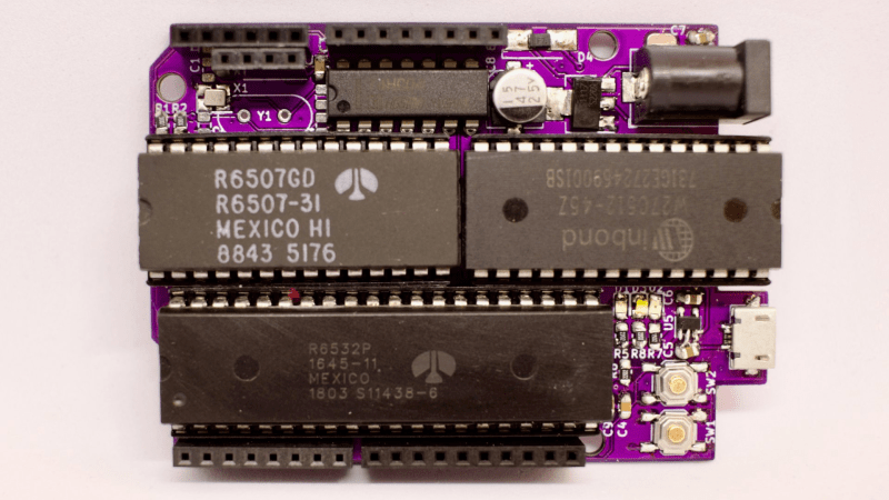
[Anders Nielsen] presents his entry for the 2023 Hackaday Prize: The 65uino. Which as you might be able to guess, is a 6502-based microcomputer wedged into an Arduino Uno form factor (well, almost wedged in, but we’ll let it slide) The premise is simple, older micros are easier to understand, the board can be build up from new-old or salvaged stock, and that’s more chips on boards and less sitting on a dusty shelf. After all, even though the 6502 in its original form is long obsolete, it’s far better to be pushing some electrons around, than sitting there decaying.
From an educational perspective, the first lesson is the hand-soldering of through-hole DIP components and a smattering of straightforward surface mount parts in their supporting roles. Then on to setting up the cc65 toolchain. To say this is a pure 6502 system is a little misleading, it actually uses the 6507 device variant, which is a die-bond variant of the same device but with only 28 of the pins utilized.
The use of the 6532 RIOT (RAM-I/O-Timer) chip provides two 8-bit ports of GPIO as well as a timer and 128 bytes of SRAM, making the design more compact. There is a socket that will accept a 24 or 28-pin E(E)PROM device, with the extra four pins removable and the PCB snapped off if fitment into a standard ‘Uno case is desirable. Neat!
Full hardware build and PCB design (using KiCAD) are available on the 65uino GitHub page. Just remember folks, with everything minimal 6502 related — some assembly required :D
We see the 6502 a lot, let’s be fair. But why not? Here’s a slightly more practical board with a bit more resources, an absolute beast of a luggable dual-6502 machine, and yet another 6502 verilog implementation ready to be dropped into a spare corner of a FPGA project that needs a little extra.


OK, That’s a perfect practical joke, but we’re in May, April 1st is now gone. I fail to see the point in actually helping education.
Lemme try to win you over then.
The 6502 has 56 instructions – the ATMega328p has 131.
The 328 has 10 bit ADCs, 8 and 16 bit timers, 32Kb flash, 1k of eeprom, 2KB of SRAM, internal oscillators and even comparators – all in a single package. The 6502 has neither.
Just the datasheet for the 328 is almost 300 pages long – and I bet a first time user isn’t any closer to understanding how a computer works after reading it :)
By separating the features the system does have into three packages that each do their part, but can almost be fully explained in about 20 minutes is a way better learning experience.
This way it’s a fun soldering project, a fun retro build and an easy way to learn the basic parts of most computers and micros without getting burnout on day one.
Good luck to all participants and I hope everyone else will enjoy the ride! :)
heh i think the fact that you are putting work into it is what makes it valuable to the people you touch. so – thank you and good luck! but i disagree with everything you just said :)
my first embedded chip was an 8051 (DS5000), and i got ahold of it by begging a distributor to send me a sample — so i received a bound hardcopy of its datasheet! woo! reading a PDF on the computer in 1997 was a whole different struggle. anyways, i read that book i think cover to cover, and i learned just a bunch. it was a perfect primer to embedded development. the sort of information it gives you is such a good introduction to the sort of questions you will ask when doing embedded development.
the most important thing i learned from it is the structure of an embedded datasheet. i have barely even glanced at atmel documentation (i’m a pic fan) but i can tell you right off…it has a pinout, a high-level schematic for the I/O drivers, a memory map, a chapter for each of the peripherals (with a single table register summary at the front and a detailed breakout of each register separately at the end), a chapter on the instruction set (with a single table summary, again followed by break-outs with details like timing), a description of power consumption, electrical characeteristics of (mA, V, rise and fall times), a chapter on programming (ICSP or whatever), and finally a chapter on the mechanical dimensions of the chip.
even using the rp2040 today, which has a decidedly unique approach to the datasheet…all those old elements are there. reading the ds5000 datasheet when i was 17 perfectly prepared me. i now know how to use a SoC reference manual, how to skip to the part i want. and, like, ARM chips these days separate that datasheet into several documents, so if i only find the summary table, i now have the confidence to say “there is a part i’m missing, let’s go back to the website”.
some people do need a little more help when they get started but i hate starting with pidgin things. start in the real world. i think people are able to appreciate it.
of course the real challenge a lot of times is to relate to an audience that doesn’t even necessarily want to be there, and isn’t interested in developing a high level of competence and familiarity. a lot of challenges out there and this might be the best for some! i just think the idea that the atmega datasheet is complicated just because it’s long and complete is bogus. it’s exactly wrong. it’s a very simple datasheet and a great primer to what it’s like to use reference materials.
Thank you for the perspective – it looks to me like you took the hard way around if you think the 328p datasheet is a great primer :D
Teaching is hard and students are attracted to different things.
I certainly don’t believe 2/3rds of an Atari 2600 in a usable form factor is a “pidgin thing” – it’s the real thing, without the baggage of 50 years cluttering up the view.
Some learn notes and scales first and become Mozart.. Some learn three chords and become Bob Dylan.. The 65uino is more of a Dylan thing ;-)
The 328 datasheet is pretty difficult for even a somewhat experienced electrical engineer to read and get any of the multi register hardware functions working. I’m saying this watching my coworkers, who design IC’s, email hey how do I get the ADC in free-running mode?
The big advantage of the 328 ecosystem is that someone else already did it and has code online for you to copy.
Indeed, just because something is very complicated and has lots of features doesn’t mean it’s not approachable. You can learn a little bit at a time, provided that you have tools that allow you take it in step by step.
People who start with microcontrollers tend to not learn as much about computers’ innards. This is an area where using a 6502 becomes helpful. A microcontroller makes for fewer parts; but it’s not necessarily easier to develop stuff on. In 2021 I had to re-develop something to work on a PIC16 after I had done it a couple of years earlier on my workbench computer with the 65c02. Even though I had the previous work to go on, and even though I’ve brought a dozen products to market using PIC16’s, doing this project again for the PIC16 was much, much harder than it was on the 65c02. There are 65c02-based microcontrollers of course, but must of them are ASICs, going into automotive, industrial, toy, and even medical applications.
I googled a generic 6502 datasheet and having programmed interpreted c on a 68k chip… Wow dude, I can see the appeal here.
The advantage of having all those peripherals in the atmel is that it allows the device to be used for fun projects, which keeps people interested and helps with the education. The 6502 system is easier to learn, but people are quickly going to hit the limits of the system, and quit using it.
Most people don’t program the Atmel in assembly language, but use the arduino ide, and the easy libraries.
And the 56 vs. 131 instructions make what difference when you’re programming it in C? Not to mention the fun beginners are going to have dealing with trying to use C on a system with only 128 bytes of RAM where the zero page and stack are co-resident in mirrored address space.
I am also not totally buying that adding SMD devices to the list of things to be soldered is terribly beginner-friendly.
Maybe it’s not meant to be programmed in C, since that also obscures the innards of the system ;-)
High level languages aren’t always the best choice. If you start with assembly you will eventually figure out the practicality of higher level languages – if you start with C you may never find out why you sometimes don’t need C.
If someone wants to teach using this as a class set, it’s up to them to decide if they also want it to be an SMD soldering class or not.
If not then all SMD parts are generic and most board houses will supply and solder that side of the PCB for you cheap.
6502 are meant to be programmed in machine language such as using a 6502 assembly language tools etc (machine language represented using mnemonics) or in hexadecimal format using a machine language monitor.
Just needs a way to plug in a TIA chip and you’ve got an Atari 2600.
Was going to mention this. 65uino is basically 2/3 of an Atari 2600 system.
More like 3/4; it includes the game ROM.
Looking at this as an educational project, the biggest problem I see is not being able to get code onto it (without extra hardware). Plugging and unplugging 24-28 pin DIPs is not practical in an educational environment. The sacrifice to get to the small form factor seems too much for me.
It’s actually not meant to be used that way most of the time – I have a “solution” but I’m about a month away before I’m ready to publish :)
We might want to update to the newest cc65 sure on GitHub. https://cc65.github.io/
Blows my mind there are TWO cc65 websites for like a decade..
The cc65 docs are written in freaking SGML.. way to discourage any users from ever helping.
No wonder so many communities wrote their own cc65 docs rather than try to participate.
Great tool, awful project and leadership.
This is awesome! I’ve had this exact same project in mind for several years, and I’m so glad you are making it a reality. Now you’ve saved me the time of developing it so I can dive in with a head start.