There’s much truth in the advice that, to truly understand something, you need to build it yourself from the ground up. That’s the idea behind [Christian]’s entry for the Re-engineering Education category of the 2023 Hackaday Prize. Built as an educational demonstrator, this is a complete arithmetic-logic unit (ALU) using discrete relays — and not high-density types either — these are the big honking clear-cased kind.
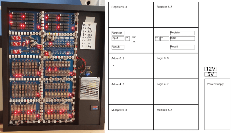
The design is neatly, intentionally, partitioned along functional lines, with four custom PCB designs, each board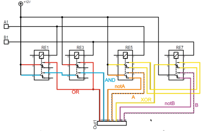 operating on 4-bits. To handle a byte-length word, boards are simply cascaded, making a total of eight. The register, adder, logic function, and multiplex boards are the heart of the build with an additional two custom boards for visualization (using an Arduino for convenience) and IO forming the interface. After all, a basic CPU is just an ALU and some control around it, the magic is really in the ALU.
The fundamental logical operations operating upon two operands, {A, B} are A, ~A, B, ~B, A or B, A and B, A xor B, can be computed from just four relays per bit. The logic outputs do need to be fed into a 7-to-1 bit selector before being fed to the output register, 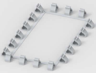 but that’s the job of a separate board. The adder function is the most basic, simply a pair of half-adders and an OR-gate to handle the chaining of the carry inputs and generate the carry chain output.
3D printed cable runs are a nice touch and make for a slick wiring job to tie it all together.
For a more complete relay-based CPU, you could check out the MERCIA relay computer project, not to mention this wonderfully polished build.


I like the 4-relay-per-bit thing. It’s so nice to try and make logic when you can manage to get the inputs and their complements at full strength as well as at least some of the other operations.
At one point I was interested in seeing what minimum number of relays would be needed to do various operations needed if you wanted to track the time by following mains AC using relay logic. In thinking about the boolean operations, I quickly decided that it would be helpful to allow diodes and assume the relays could switch with quite a bit less than the full rail voltage. A lot like how in designing a silicon chip you optimize the size of transistors so that each stage is big enough to drive the inputs of the next stage, except my objective was to use the fewest relays no matter if the rise and fall time suffers a bit.
Since I was thinking of typical 5-terminal relays, rather than the DTDP pictured here which throw two switches, it’s hard to keep the relay count down without dumb hacks. My single relay “and” would be wired to use whichever between A and B was driven more weakly to energize the coil and then pass through the other value when energized, because logically anything AND true is just itself. Kind of like playing with muxes. An “or” is easy of course; just connect the wires together with diodes to prevent A from affecting B and vice versa. Sometimes the end-goal circuit is simpler if you go around and invert the values at certain points in the logic, too. That’s easy enough if you remember a relay is in one state if its inputs are equal *or floating*, and the other state if they are different and neither is floating.
I never finished that project; once I got done looking at the various logic operations I got bored trying to decide if I should allow bistable relays or what kind of latching/memory to use to make the clock divider.
With a different set of assumptions in the MERCIA project mentioned in the article, you get this set of elements. https://www.relaiscomputer.nl/index.php/elements
I think I’ve heard proposals to use relays, maybe mems switches, as a high temperature computer for Venus exploration.
And of course, if nothing else you can do little tricks with them like make them a self-excited buzzer and sometimes make use of the AC (really interrupted DC, but hey) for something else.
Relay projects are fun! Throw in magnetic amplifiers if you want to really make people think.
Gallium fluidic computer.
SPDT relays are a PITA for practical computing so… I tried to make one ! https://hackaday.io/project/20864-ygrec-15-bis It didn’t succeed yet but I developed quite interesting methods. I hope to make a 8- bit processor someday anyway ;-)
I like it!
I also looked at the MERCIA project but I wanted no diodes in the logic (other than the LEDs and the flyback diodes) and have the logic as “simple” as possible to understand – with the cost of more (and more expensive and bigger) DPDT relay.
A possible improvement could be to repurpose the red and blue signals for A, ~A, B, and ~B and free up the orange and purple signals for creating a NXOR, also known as an EQ or ==, which would be pretty useful for an ALU.
PCB Gerbers?
I will add them