[Adrian Smith] recently scored an avionics module taken from a British Aerospace 146 airliner and ripped it open for our viewing pleasure. This particular aircraft was designed in the early 1980s when the electronics used to feed the various displays in the cockpit were very different from modern designs. This particular box is called a ‘symbol generator’ and is used to generate the various real-time video feeds that are sent to the cockpit display units. Various instruments, for example, the weather radar, feed into it, and it then reformats the video if needed, mixing in any required additional display.
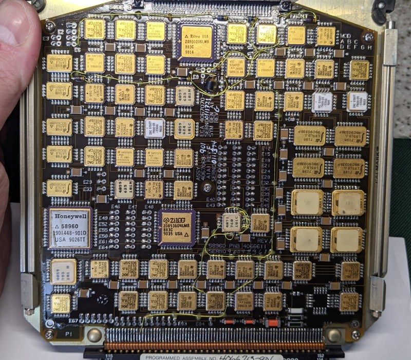
There are many gold-plated chips on these boards, which indicates these may be radiation-hardened versions of familiar devices, most of which are 54xx series logic. 54xx series logic is essentially the same functionally as the corresponding 74xx series, except for the much wider operating temperature range mandated by military and, by extension, commercial aviation needs. The main CPU board appears to be based around the Intel 8086, with some Zilog Z180 compatible processors used on the two video display controller boards. We noted the Zilog Z0853604, which is their counter/timer/GPIO chip. Obviously, there are many custom ASICs produced by Honeywell as well as other special order items that you’ll never find the datasheet for. Now there’s a challenge!
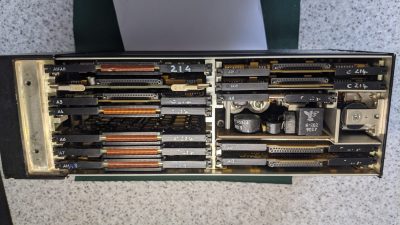
Finally, we note the standard 400 Hz avionics-standard power supply, which, as some may know, is the standard operating frequency for the AC power system used within modern aircraft systems. The higher frequency (compared to 50 or 60 Hz) means the magnetic components can be physically smaller and, therefore, lighter for a given power handling capability.
We see a lot of avionics teardowns, likely because they’re fascinating. Here’s some more British military gear, an interesting RF distance measuring box from the 1970s, and finally, some brave soul building their own avionics gear. What could possibly go wrong?


I like this kind of content.
I have a bare PCB for a more modern version of this, circa 2006. It was scrap in the bin of the PCB factory I worked in at the time, I think one (of 14!) of the inner layers failed X-ray inspection.
The basic layout is similar; it’s rectangular, somewhere between A4 and A5 paper sizes with big connectors on one long edge to plug into a backplane, and I think VGA connectors on the other long edge.
At the time it was a quite dense board, one side with lots of BGAs and other ICs crammed in, and some ICs and a whole load of 0402 and 0603 decoupling caps on the other side. There are so many vias that the board looks transparent with light behind it.
I’ve kept it as a conversation piece for when I’m visited by fellow nerds. Being a bare board though it’s quite mysterious, it’s nice to see something similar but populated.
It would be good to see a photo of it
TIL aircraft use 400hz AC! The magnetic thing the article notes is for transformers and such, right?
Yes the large module is the 115v 400hz AC to DC power supply unit.
Aircraft use 400 Hz AC because it reduces the iron needed in transformers and motors by 80% compared to 60 Hz.
And causes havoc when in surplus, because you need a 400cycle power supply.
The transformers are reasonable for auduo frequencies.
That looks expensive.
Still, certification probably was the most expensive part of it
Quite a few bodge wires going on here. I guess getting a PCB of this complexity right first time was a big ask back then.
Rad hard? No, that was space level stuff, a super tiny percentage amount of ICs. And they were rad hard survivors, not ‘hardened’.
Put them in a gamma source, if they survived, they were hard.
Gold plating because it was once cheap, $32.50 a troy oz, and it worked well for hermetic packages.
So why have some of it hardened and some not? What good does it to save some of it when the rest fails!
Why do you think it’s going to fail? Exclamation points are unnecessary. RADHARD logic is only needed in space and nuclear research. The highest spec chips with the best temperature range and full certification testing are RADHARD parts even though resistance to radiation is not necessary here. It’s still a feature and there are other benefits which come from those fabrication techniques and product lines which led to their selection.
So, is it hard to de-solder those parts when there is coating on the PCB? I mean you could reuse those 54xx IC’s and various other bits that aren’t prone to fail quite as much as electrolytic capacitors.
Yeah its quite difficult to unsolder components from boards coated with a thick layer of conformal coating. Risk damaging the part and the board. I likely won’t use any parts from this, just keep it as-is.
I’m not seeing any rad-hard part numbers. Typically, you’ll see an R after the 5962 prefix in parts that have SMD part numbers. The 54HC chips do have some radiation tolerance but that’s mostly just due to how old of a design they are. This is just mil spec ceramic flat packs. Basically, just a standard way of making “smaller” chips for applications that have higher reliability needs (temperature, shock, vibration, etc).
I didn’t know that. I assumed with them being gold topped they were radiation hardened. Good to know.