DME With A Twist Of LimeSDR

Navigating aircraft today isn’t like the old days. No more arrows painted on a barn roof or rotating airway beacons. Now, there are a host of radio navigation aids. GPS, of course, is available. But planes often use VOR to determine a bearing to a known point and DME — distance measuring equipment — to measure the distance to that point. DME operates around 1000 MHz and is little more than a repeater. An airplane sends a pair of pulses, and times how long it takes for the DME to repeat them. [Daniel Estévez] has been monitoring these transmissions with a LimeSDR.

Like most repeaters, the DME transponders listen on one frequency and transmit on another. Those frequencies are 63 MHz apart. This poses a challenge for some types of SDRs which have limits on bandwidth.

Continue reading “DME With A Twist Of LimeSDR”

Unlocking The Mystery Of An Aircraft ADI

If you’ve ever seen the cockpit of an airplane, you’ve probably noticed the round ball that shows your attitude, and if you are like us, you’ve wondered exactly how the Attitude Direction Indicator (ADI) works. Well, [msylvain59] is tearing one apart in the video below, so you can satisfy your curiosity in less than 30 minutes.

Like most things on an airplane, it is built solidly and compactly. With the lid open, it reminded us of a tiny CRT oscilloscope, except the CRT is really the ball display. It also has gears, which is something we don’t expect to see in a scope.

Continue reading “Unlocking The Mystery Of An Aircraft ADI”

Inside A Mystery Aerospace Computer With [Ken Shirriff]

When life hands you a mysterious bit of vintage avionics, your best bet to identifying it might just be to get it in front of the biggest bunch of hardware hounds on the planet. After doing a teardown and some of your own investigation first, of course.

The literal black box in question came into [Ken Shirriff]’s custody courtesy of [David] from Usagi Electric, better known for his vacuum tube computer builds and his loving restoration of a Centurion minicomputer. The unit bears little in the way of identifying markings, but [Ken] was able to glean a little by inspecting the exterior. The keypad is a big giveaway; its chunky buttons seem optimized for use with the gloved hands of a pressure suit, and the ordinal compass points hint at a navigational function. The layout of the keypad is similar to the Apollo DSKY, which might make it a NASA artifact. Possibly contradicting all of that is the oddball but very cool electromechanical display, which uses reels of digits and a stepper-like motor to drive them.

Inside, more mysteries — and more clues — await. Unlike a recent flight computer [Ken] looked at, most of the guts are strictly electronic. The instrument is absolutely stuffed with PCBs, most of which are four-layer boards. Date codes on the hundreds of chips all seem to be in the 1967 range, dating the unit to the late 60s or early 70s. The weirdest bit is the core memory buried deep inside the stacks of logic and analog boards. [Ken] found 20 planes with the core, hinting at a 20-bit processor.

In the end, [Ken] was unable to come to any firm conclusion as to what this thing is, who made it, or what its purpose was. We doubt that his analysis will end there, though, and we look forward to the reverse engineering effort on this piece of retro magic.

The World’s First Microprocessor: F-14 Central Air Data Computer

When the Grumman F-14 Tomcat first flew in 1970, it was a marvel. With its variable-sweep wing, twin tail, and sleek lines, it quickly became one of the most iconic jet fighters of the era — and that was before a little movie called Top Gun hit theaters.

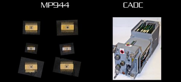
A recent video by [Alexander the ok] details something that was far less well-documented about the plane, namely its avionics. The Tomcat was the first aircraft to use a microprocessor-driven flight system, as well as the first microprocessor unit (MPU) ever demonstrated, beating the Intel 4004 by a year. In 1971, one of the designers of the F-14’s Central Air Data Computer (CADC) – [Ray Holt] – wrote an article for Computer Design magazine that was naturally immediately classified by the Navy until released to the public in 1998.

The MPU in the CADC is called the Garrett AiResearch MP944, and consists of a number of ICs that together form a full computer. These were combined in the CADC with additional electronics to control many elements of the airplane automatically, including the weapons system and the variable-sweep wing configuration. This was considered to be essential based on experiences with the F-111 and its very complex electromechanical flight computer, which was an evolution of the 1950s-era Bendix CADC.

The video goes through the differences between the 4-bit Intel 4004 and the 20-bit MP944, questioning whether the 4004 is even really an MPU, the capabilities of the MP944 and its system architecture. Ultimately the question of ‘first’ and that of ‘what is an MPU’ will always be somewhat fuzzy depending on your definitions, but there is no denying that the MP944 was a marvel of large-scale integration.

Continue reading “The World’s First Microprocessor: F-14 Central Air Data Computer”

Teardown Of FGM-148 Javelin Missile’s Guidance Computer

You know it’s a good teardown when [Michel] starts off by saying to not ask him where exactly he got the guidance section of an FGM-148 Javelin from. This shoulder-launched anti-tank guided missile (ATGM) is a true marvel of engineering that has shown its chops during recent world events. As a fire-and-forget type guided missile it is designed to use the internal IR tracker to maintain a constant lock on the target, using its guidance system to stay exactly on track.

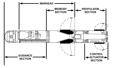
FGM-148 Javelin schematic overview. (Source: U.S. Army, FM 3-22.37)

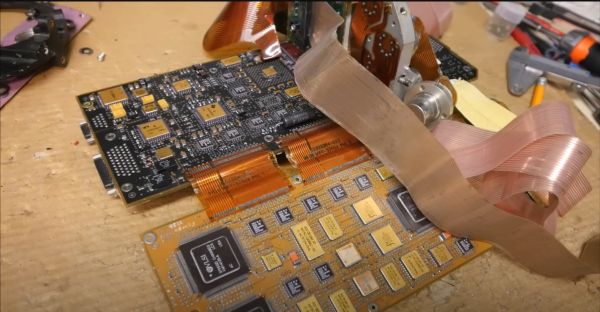
Initially designed in 1989 and introduced into service in 1996, it has all the ceramic-and-gold styling which one would expect from a military avionics package from the era. Tasked with processing the information from the IR sensor, and continuously adjusting the fins to keep it on course, the two sandwiched, 3 mm thick PCBs that form the main section of the guidance computer are complemented by what looks like a milled aluminium section which holds a sensor and a number of opamps, all retained within the carbon-fiber shell of the missile.

In the video [Michel] looks at the main components, finding datasheets for many commercially available parts, with the date codes on the parts confirming that it’s a late 80s to early 90s version, using presumably a TMS34010 as the main CPU on the DSP board for its additional graphics-related instructions. Even though current production FGM-148s are likely to use far more modern parts, this is a fun look at what was high-end military gear in the late 1980s and early 1990s.

Continue reading “Teardown Of FGM-148 Javelin Missile’s Guidance Computer”

Open Source Spacecraft Avionics With NASA’s Core Flight System

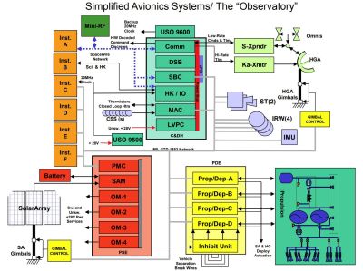
One thing about developing satellites, spacecraft, rovers and kin is that they have a big overlap in terms of functionality. From communication, to handling sensors, propulsion, managing data storage, task scheduling and so on, the teams over at NASA have found over the years that with each project there was a lot of repetition.

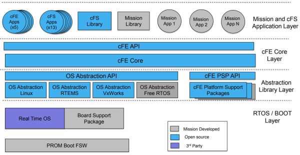
Block diagram of a simplified avionics system. (Credit: NASA)

Either they were either copy-pasting code from old projects, or multiple teams were essentially writing the same code.

To resolve this inefficiency NASA developed the Core Flight System (cFS), a common software framework for spacecraft, based on code and lessons from various space missions. The framework, which the space agency has released under the Apache license, consists of an operating system abstraction layer (OSAL), the underlying OS (VxWorks, FreeRTOS, RTEMS, POSIX, etc.), and the applications that run on top of the OSAL alongside the Core Flight Executive (cFE) component. Here cFS apps can be loaded and unloaded dynamically, along with cFS libraries, as cFS supports both static and dynamic linking.

There are a few sample applications to get started with, and documentation is available, should you wish to use cFS for your own projects. Admittedly, it’s a more complex framework than you’d need for a backyard rover. But who knows? As access to space gets cheaper and cheaper, you might actually get the chance to put together a DIY CubeSat someday — might as well start practicing now.

Vintage Artificial Horizon Is Beautiful In Motion

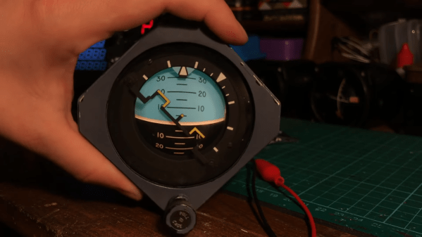
Attitude indicators are super useful if you’re flying a plane, particularly in foggy conditions or over water. They help you figure out which way the plane is pointing relative to the unforgiving ground below. [Hack Modular] has been toying with a few, and even figured out how to get them powered up!

The attitude indicators use spinning gyroscopes to present a stable artificial horizon when a plane is in motion. Airworthy models are highly expensive, but [Hack Modular] was experimenting with some battered surplus examples. He sets about opening the delicate gauges, noting the seals and other features intended to protect the equipment inside. We get a great look at the gimbals and the reset mechanism used to zero out the device. He then pulls a classic mechanic’s trick, robbing a few screws from Peter to reassemble Paul.

We wouldn’t trust the gauges for flight duty, but they look great when powered up, all lit and spinning. They have the beautiful vintage glow that you only get from filament bulbs and deftly painted instrumentation. While avionics don’t come cheap off the shelf, it’s worth tinkering with cheap older gear if you can find it. The engineering involved, even in older equipment, is truly impressive. Video after the break.

Continue reading “Vintage Artificial Horizon Is Beautiful In Motion”