As boring as propeller designs may seem to the average person, occasionally there’s a bit of a dust-up in the media about a ‘new’ design that promises at least a few percent improvement in performance, decreased noise profile, or any combination of such claims. Naturally, if you’re [Daniel Riley] of RCTestFlight, then you have to 3D print a few of them, and make a video covering a handful. Most famous of these is probably the toroidal propeller that made waves a while ago, mostly in the field of flying drones, but commercial toroidal boat props exist too.
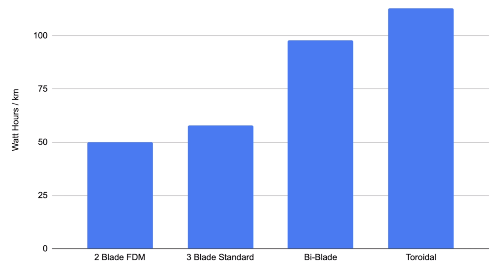
Interestingly, the 2-blade FDM-printed propeller ended up performing the best, while the bi-blade design (with two sets of blades positioned one after the other) performed worse — but better than the toroidal design. Here the last two designs were professionally printed in nylon, rather than printed at home in a standard FDM printer with all of the surface sanding and treatment required. Even so, the surface treatment did not seem to noticeably affect the results in further testing.
Hints at the root cause of the problem came from the bubble tests. In a bubble test, air is blown in front of the spinning propeller to visualize the flow of the water. This revealed some stalling on the bi-blade and the toroidal design too, which would explain some of the performance loss. Going back between the CAD model and the design in the patent by Sharrow Marine didn’t provide any obvious hints.
Considering that this latter company claims a performance uplift over regular boat propellers, the next steps for [Daniel] would appear to involve some careful navigating between fluid dynamic modeling and claims made in glossy marketing material to figure out exactly how close someone at home with a 3D printer and some spare time can get to those claimed numbers.
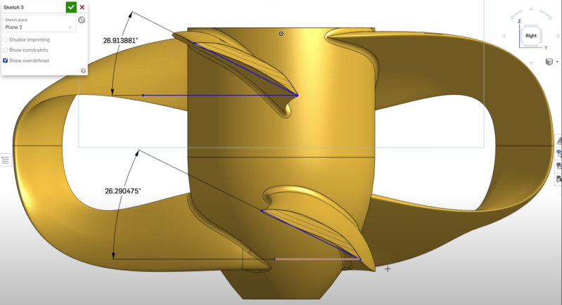
(Heading image: The toroidal propeller’s details in the CAD software. (Credit: rctestflight) )


My limited instinct tells me those are going to cavitate, leading to increased wear, decreased lifetime and degraded performance.
One thing you could do is look into nuclear submarine props… while those designs are mostly classified, there is enough OSI out there to derive a basic shape that is specifically made to be efficient, quiet, and eliminate cavitation. Seems like most have a high, odd blade count and a tapered, “wrapped” profile. Some even went to ducting/cowling.
The YouTuber “SubBrief” might be one such source. He was a submariner and always talks about the props when he can in his video essays… at least on non-NATO vessels.
At least when it comes to nuclear subs, those are probably optimised heavily towards low noise rather than efficiency. While these are related goals (noise is wasted energy after all), I bet a lot of effort has gone into tuning the specific noise profile to be something that doesn’t have a distinct signature (i.e. the energy is spread across a wide range of frequencies or is designed to blend in with natural background noise).
On a peripherally related subject, has anyone done a study of how noise from a small, recreational fishing boat affects fish? If negatively with respect to presence and willingness to take the bait, perhaps a stealthier boat and trolling motor would be productive?
When I went camping a kid, it was common to use an electric outboard motor when fishing in quiet rivers so as not to spook the fish.
Indeed, and a lot of those are fairly simple two-blade tapered props.
Not a good idea to take submarine props as an example. Cavitation is generally not a problem for submarines, as cavitation is related to the hydrostatic pressure, which boils down to the immersion of the propeller. That’s why their blades can have a relatively low chord length without them cavitations.
They are indeed optimised for low noise. What you are referring to as tapered and wrapped profile is called skew. When the blades overlap, the pressure peaks of each blade do as well, leading to less pronounced pressure peaks over all. It’s not that great for efficiency though…
isn’t scale a factor here?
Often the more basic the design it, the more tolerant it is for operating out of its ideal conditions. Fancy designs probably require optimization for specific parameters, like rotational speed, optimum torque, operating depth and flow rate.
Yes, and the deflections due to the material probably affect the running shape of the blades very differently
I don’t know anything about hydrodynamics….but….
For the torroidal design, doesn’t the pitch of the lower blade need to be higher than the upper one? Won’t that effect the amount of flow through that section of the propeller? Moving more fluid at the top and less at the bottom is sort of the direct cause of the stall, isn’t it?
I’m probably missing something obvious to those practiced in the art.
willmore: Yes indeed, while there are few contra-rotating propellers in the marine market, the aft propeller eeds to have somewhat greater pitch than the forward propeller in order for the overall design to be optimised. That is because the aft propeller is operating in the ‘slipstream’ of the forward propeller. The same would have to apply to a toriodal propeller even if both ‘sets’ of lades are turning in the same direction.
Wouldn’t a toroidal water propeller get fouled more easily?
There may also be a problem with the material used
Pushing a prop through water meets a lot more resistance, (yep water denser than air)
If your prop is nylon is will be more flexible and more prone to vibration, creating cavitation
A metal prop, like bronze alloy is more rigid and that may make them more efficient
Much like wind turbines, my understanding is that the most efficient prop is a single traditional blade, everything else is drag added as a compromise for other reasons (maintaining sensible sizes, improving efficacy over efficiency etc). It’s hard to see how adding more surface area would improve efficiency. Adding a shroud is almost always the best way to improve prop performance IIRC
I wonder if the connecting parts between the blades could be thought of as built-in shrouds with the benefit of being able to be shaped to provide extra thrust?
Some of the benefit of a shroud, without the bulk of a shroud maybe.
James: It is typically possible to ‘eek out’ a few more percent of efficiency from a contra-rotating propeller than a regular optimised propeller of same diameter, thrust etc. That is because the contra-rotating propeller leaves less swirling water behind it and hence less energy is lost. But like you, I don’t think a toroidal propeller has any magic additional efficiency over a well designed regular propeller.
What about a regular prop with winglets?
That has indeed been done. It is referred to as the Contracted Loaded Tip propeller, see for example: https://www.sistemar.com/en/clt-propellers/
I am somewhat unconvinced by the “Test results of the different boat propeller designs. (Credit: rctestflight)” shown in this article. The comparison is made on the basis of Wh/km. This would e fine if the comparison between all four props was on a craft achieving the same average speed over the measured distance. But what is to say that the toroidal propeller craft wasn’t actually running slower than the other cases being considered. Drag, and hence thrust required to move a craft through the water or air is typically proportional to velocity squared. So it takes much less energy to move a craft over a fixed distance if you do it slowly than if you try to do it quickly. If we assume the craft were indeed all moving at the same speed, then a rule of thumb for a well designed regular marine propeller is that it is about 60% efficient. For the toriodal propeller to achieve around 115 Wh/km while the regular prop achieved only about 60 Wh/km, the toroidal prop would have to have a 115% efficiency. There is no such thing as a propulsor that delivers more than 100% efficiency.
You’re making a mistake here. 115 Wh/km is more inefficient than 60 Wh/km.
However, I am also doubting the claimed numbers in other sources for the same reason you’re mentioning.
I, too, don’t know much about hydrodynamics, but…
Shouldn’t there be a half-twist in the foil loop? I thought the whole point of closing a foil was to eliminate the tip vortex created from the pressure differential on each side of the foil. If the foil loop simply folds over, as shown in the render, the high pressure from the bottom foil runs up the loop to the low pressure of the top foil. Same for the outside. That might explain why it performs worse than a standard prop. Two vorteces (?) are created instead of one, and they shear together behind the foil.
A half-twist would make sure the foils connect to the same surfaces, and similar pressures.